 |
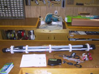
The kit comes complete with 4 tubes (2 - 38" and 2 -
50"), control box, distribution box, wiring, clips and instructions.
Be sure to read and understand the instructions before you proceed
with the project.
|
|
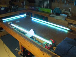 |
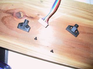
First thing is to check to make sure the lights all work
before installing on the car (yes, the fourth one works, just
not in the picture). Hooked the wires up to the battery for testing.
|
|
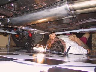 |
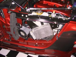
Looking for the best place to locate the tubes. See below
for final locations.
|
|
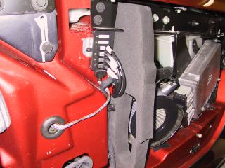 |
There are several places to put the distrbution box, this
is where we decided, behind the side panel. Secured it in place
with 3M double sided tape. Ran the flat wire that goes to the
control box through the top grommet. Ran the wiring for the power
switch through the bottom grommet.
|
|
 |
It was necessary to remove the cover to the wiring harness
in order to get it through the hole. Replace cover once the wiring
is through the hole
|
|
 |
Ran the power wires from the battery, along side the upper
frame where the side panel secures, back down to the lower opening
(grommet) to get inside the passenger side foot well.
|
|
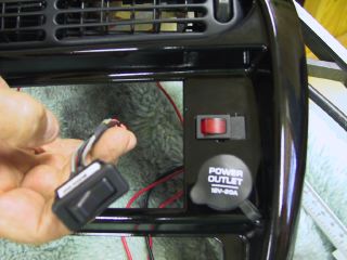 |
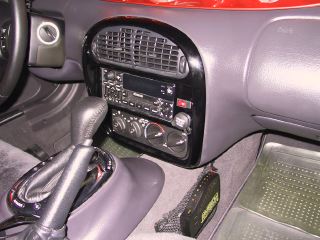
Decided that since we don't use the volume switch, that it
would be an ideal location for the light switch. Taped up the
old switch in the off position (or whatever position you normally
use) and covered it with some foam so that it won't rattle and
placed it behind the radio bezel when reinstalling. Fixed the
new switch to fit in the opening by adding a small piece of plexiglass
that was painted black and cut to fit snug in the opening.
|
|
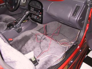 |
Now that we have all the wiring inside the foot well, just
have to place the control box (secured to the net) and hide the
excess wiring (under the floor mat).
|
|
 |
Wiring diagram. The instructions were incomplete for the
wire for the lighted switch. We finally figured it out and here
are the results. We needed to buy extra wire to run from the
battery to inside the car - need about 10 ft of two conductor
18 gauge wire. It all depends on where you are getting your power
from, we went to the battery but you could use the fuse box.
|
|
 |
Everything complete on the inside.
|
|
 |
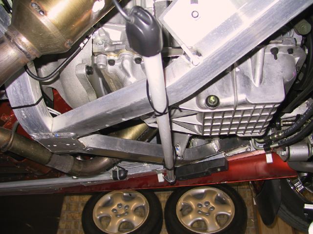
Placement of the front tube.
 click on pic for larger view click on pic for larger view
|
|
 |
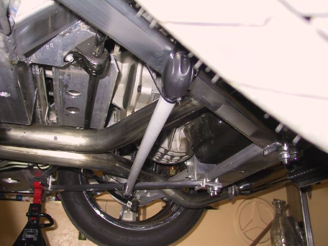
Placement of the rear tube.
click on pic for larger view
|
|
 |
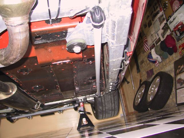
Placement of the drivers side tube.
click on pic for larger view
|
|
 |
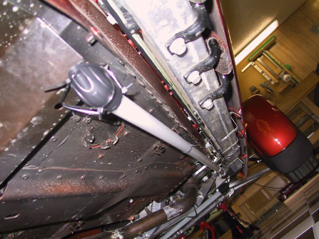
Placement of the passenger side tube.
click on pic for larger view
|
|
 |
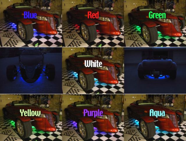
Here are pics of the final results.
click on pic for larger view
|
|