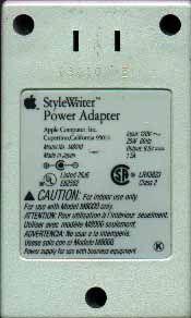
| This picture was made by putting the shell of the power pack right on a scanner, after taking out the guts. The AC plug would normally protrude from the slots making getting a good scan somewhat difficult.
On the bottom of the unit you will note the three deep, dark holes. It almost looks like there are screws in there. Nope, not so. They are little rivet-like barbed things that grab when the unit is assembled, and don't ever come back out. But if you drill out the part of the top that they hook into, the thing will come apart. |
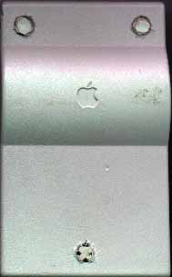
| The top is shown here with the holes already plugged back up. Drill exactly opposite the fasteners with about a 1/4 inch bit, after lining up the holes well so it doesn't look too messy when you are all done. Note that the sides of the unit are tapered so the places to drill are centered further from the corners on top than the holes are on the bottom. "Measure twice, cut (or drill) once."
In the bottom hole (the single hole at the bottom of the picture) I stuffed a couple of little pieces of ABS plastic in edgewise, with some Duco Plastic and Model Cement blobbed onto it, and later I cut the top flush. The other two holes have some round pieces of plastic from the same leftover frammis. (I've been snipping pieces, for a variety of repairs, from a disk drive carrier left over from a SPARC 1.) I just made them kinda round with wire cutters and glued them in. If I had a way to cleanly cut 1/4" disks it would look pretty decent. At least the color matches. I'll have to find another random piece of plastic in black for the other unit I'm working on as I write this page, since it came from a Portable StyleWriter. |
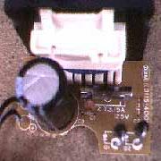
| Here's the naked unit. Typically, there's a blown fuse (such as in the middle of this picture).
Inspect the electrolytic capacitor. If it looks funky, replace it. I haven't seen that yet but it's
possible. Bend down the little disk capacitors so you can get to the leads of the fuse. Snip
the fuse leads off as close to the board as you can, but leaving a tiny bit so you can straighten
the stubs for ease of unsoldering. Unsolder from the bottom. Form the leads of the
replacement fuse like the original so it will stand off the board a bit. Such as:
 Solder the new fuse in, using 63-37 rosin core solder or as close to it as you can get. Read
here about solder. Bend the little capacitors up where they belong.
Reassemble. (Don't forget to trim off the leads after soldering.)
Solder the new fuse in, using 63-37 rosin core solder or as close to it as you can get. Read
here about solder. Bend the little capacitors up where they belong.
Reassemble. (Don't forget to trim off the leads after soldering.)
|
Drop them notes to: ebear@zianet.com