I don't have a blog, and am not interested in starting one, so as I add new information, I will add links to separate pages, here at the top.
30 Aug 2022: There is a bit of information over at the original OpenStick github
This main page was last updated 18 Aug 2022
After reading the writeup on Hackaday about the USB LTE dongle that was hacked to run Debian Linux, I had to acquire a few to play with.
I wasn't willing to order from China and wait a few weeks, so I took a chance and ordered from Amazon. There are a few different vendors selling what looks like the same thing, even using the exact same pictures (like the guy holding one up to his head). The listing showed a TF card slot, which would be handy to add additional storage.
I was lucky, and the dongles I ordered were the correct ones, with the MSM8916 chipset. However, there was no TF slot to be seen. Imagine, an inaccurate item description on Amazon.
Following the translated instructions provided by Extrowerk, I managed to install Linux on one of the dongles. I did have a few bumps along the way, as I was doing this on Windows 10, not Linux. It has been years since I did anything with Linux, so my skills are very rusty. Also, the way things are configured has changed substantially, making most of what I knew obsolete.
18 Aug 2022: A bootoader tip from Nazmul Alam Nayan.
I'll spare you the details, but here are two things that you need for Windows 10. These are not needed if you are using a Linux host with the LTE dongle.
The Fastboot driver is needed before you do anything. The RNDIS driver isn't needed until after you have booted Linux on the dongle. That's when you will see the RNDIS device in Device Manager, with no driver installed.
Following Extrowerk's instructions, things went smoothly, until I tried to install nano. I got an error "Temporary failure in name resolution".
To save others from making the same mistake I did, you need to use Activate in nmtui to connect to your home WiFi router. Select your SSID from the list, then you will be prompted for a password. I wasted hours trying to get the dongle to connect to the internet via the usb0 interface, thinking that the WiFi was to be used as an access point.
I did finally install Ubuntu on a spare PC. Once I realized that I was confused about the networking, and got it working, I see that things could have proceeded on a Windows host, as well as a Linux host.
Now that the dongle is connected to the internet, I tried to do an apt-get update, but am getting a different set of errors about the repositories.
Not being a Linux guru, I didn't know why I was getting errors with apt-get. Extrowerk pointed out that the guy who did the original work had added some Chinese repository mirrors to /etc/apt/sources.list. Looking at that file and comparing it with the official list for Bullseye here, I see that it wasn't complete. So, how to edit this file without an installed editor?
Since it was only a few lines, I saved a copy of sources.list and resorted to using echo to append each line to a new file. There is probably a better way to do this, but this worked for me. (Yes, using cat would have been a bit easier. I've forgotton a lot about Linux since I last used it.)
I was finally able to install Nano. When doing an apt-get update, I did see some errors about a Mobian repository, but since Nano is installed, I'm not going to worry about that now.
I found additonal information that I will post later.
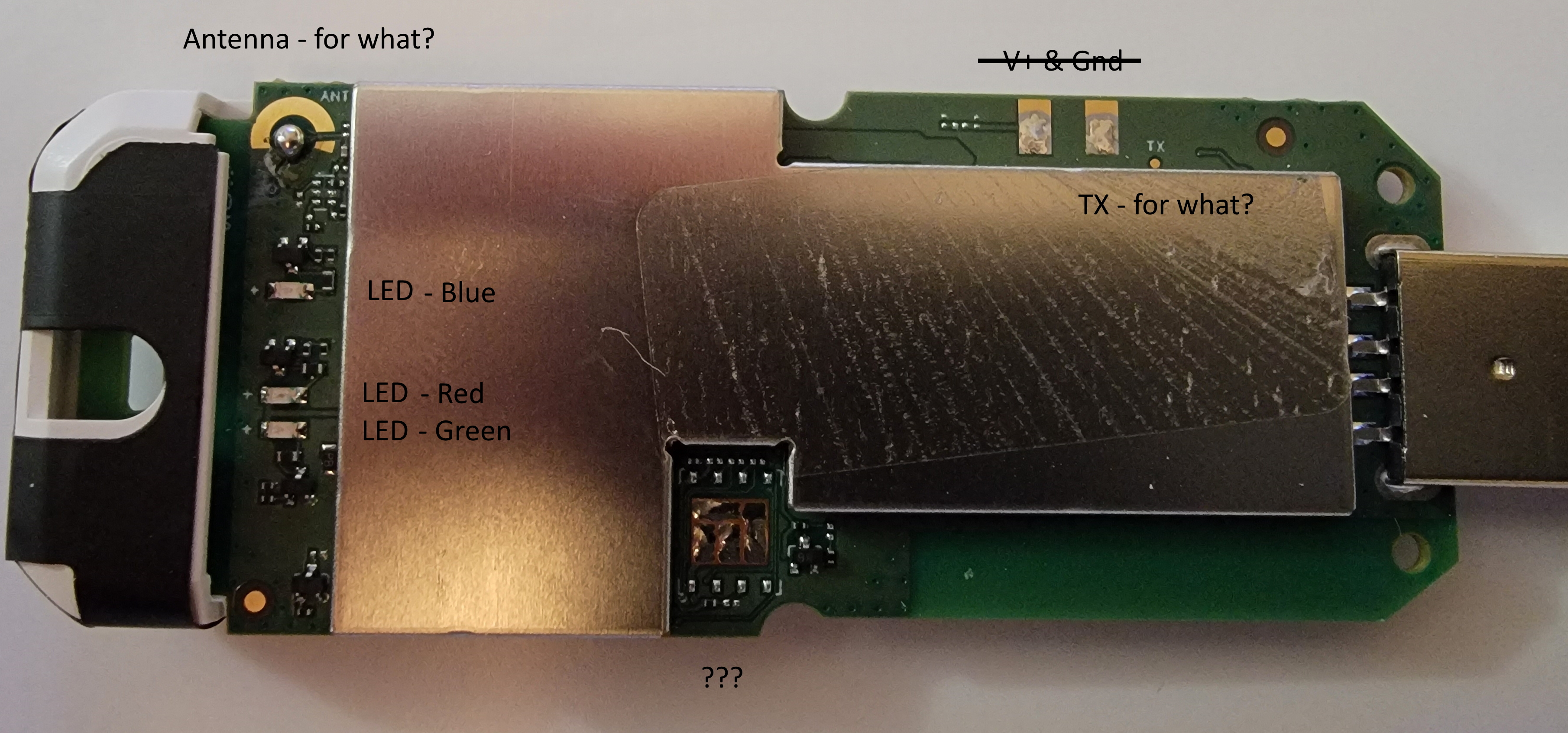
Opening the plastic case is simply a matter of three tiny screws, then prying the two halves of the case apart. Here are pictures of the top and bottom of the circuit board, with a few added notations. I'll have some additonal comments, below. Click on the pictures for a larger image.
The Qualcom MSM8916 chip, associated RF goodies, and a flash memory chip are under the metal can. No, I won't be removing it.
There are pads for an antenna, but is this for cellular, WiFi, or GNSS? There is obviously some type of tiny antenna on the circuit board for cellular and WiFi, but that doesn't preclude an external antenna. After all, these designs were intended to be used in a fully functional phone.
There are red, green and blue LEDs below the antenna pads. At various times, I saw these flashing, especially when I was trying to get the WiFi working. One may be for Bluetooth. I'll find this out later, when I try to enable Bluetooth.
I don't know what the blank area at bottom center is for. At first I thought it is was for the missing TF slot, but that is on the other side.
There is a single pad labeled TX, but I don't think it is for the UART, as there are pads for what is probably definitely the UART on the other side.
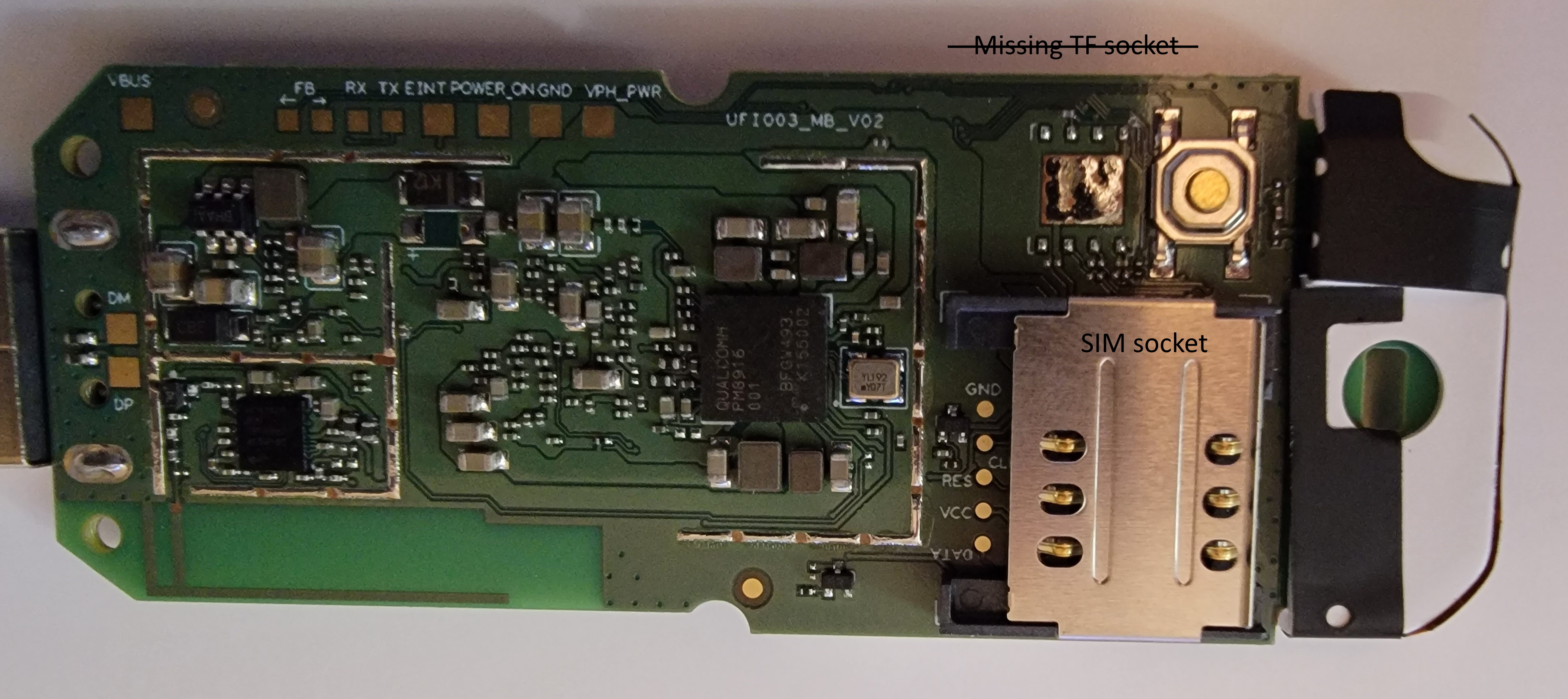
The bottom side shows where the missing TF socket should be, next to a reset button. Arya Voronova tells me that the footprint on the board is not for a TF socket, but for some type of IC. More about this later, if we can determine what this is for. There are also pads for the signals to the SIM socket, and the USB plug.
The big chip near the center is a PM8916 Power Management IC (PMIC).
What is particularly interesting is the row of pads along the top.
Some additional information I found regarding the Snapdragon 410 chipset shows that there are UART, I2C and SPI interfaces. The SPI interface is most probably used for the TF/uSD interface. Since this is missing, we may be able to interface SPI devices.
It seems that the Snapdragon 410 chipset is used by several industrial type devices, like hardened tablets, wearable devices, even development boards. A fast look at some of the information available for some of these devices looks promising. One tidbit - the buttons are GPIOs, and you can reassign the button functions from Linux. More to come, after I've read through what I've found.
With Linux installed, this dongle looks like it would be quite usable for a variety of purposes, especially if we can make use of the UART, I2C and possibly SPI to interface other hardware.
If anyone has more information, or some solid speculation, email me, and I'll update this page (you can figure out my email address from the URL of this page).