


This page may take a while to
load, but please be patient.
The thumbnails are large and detailed, and there are many images.
Click on a thumbnail to see a larger JPG image. Then use your browser's "Back" button to return to this page.
| Chesley Bonestell's "Baby Satellite" | |
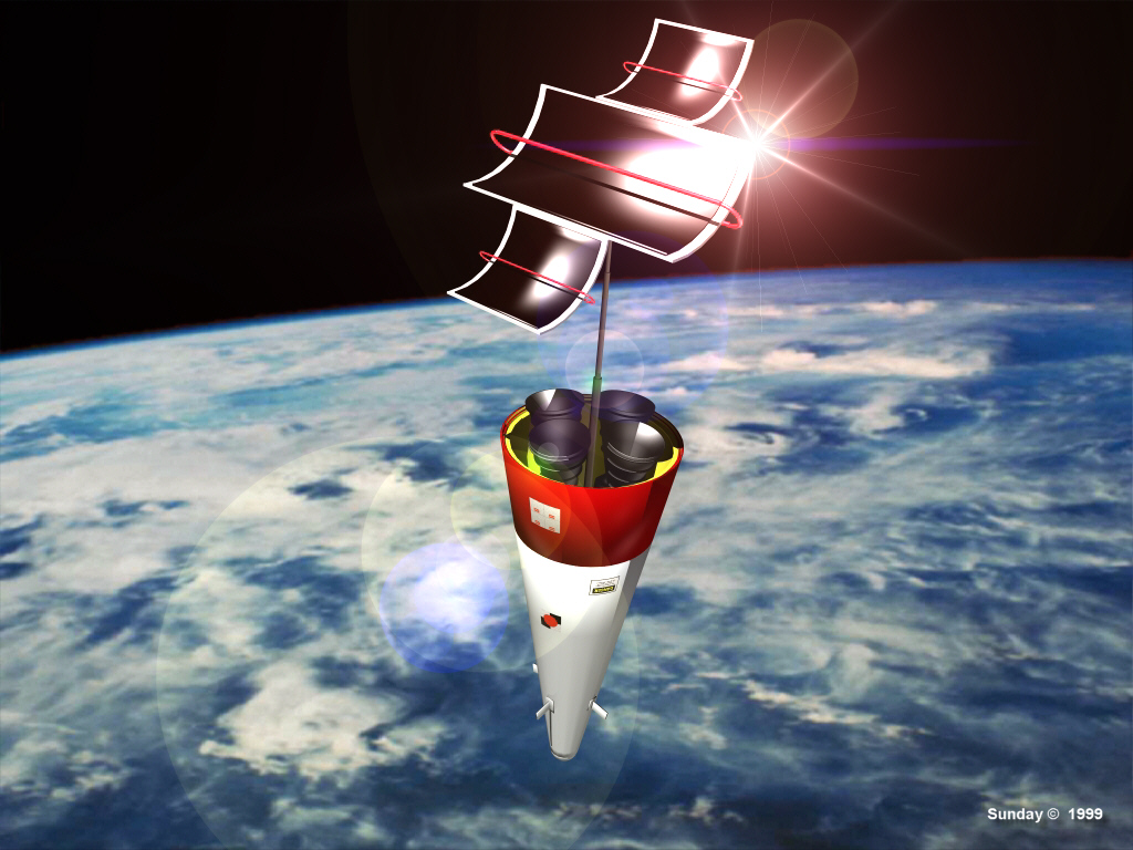 |
Chesley Bonestell (1888-1987) created space
artwork of striking beauty and superb realism. His imagination showed us stunning vistas
of spacecraft, planets, moons and other solar systems. In June 1953, over four years
before the Soviet Union launched the world's first artificial satellite Bonestell's cover painting for Collier's magazine depicted a conical,
solar-powered "baby satellite" passing 200 miles over the New Jersey coast. The satellite in this digital image is based on the one Bonestell designed. When he did his painting, solar cells had not yet been invented. The satellite got electrical power by a mercury vapor turbine. The large black panels are mirrors. They're reflecting the blackness of space. The red tubes contain mercury (which should really be silver, but Bonestell painted it red, so who am I to quibble?). The mirrors focus sunlight on the tubes and vaporize the mercury inside them, which then flows down through the central mast to drive a turbine generator inside the satellite between the rocket engine exhaust nozzles. |
| SRB Burnout | |
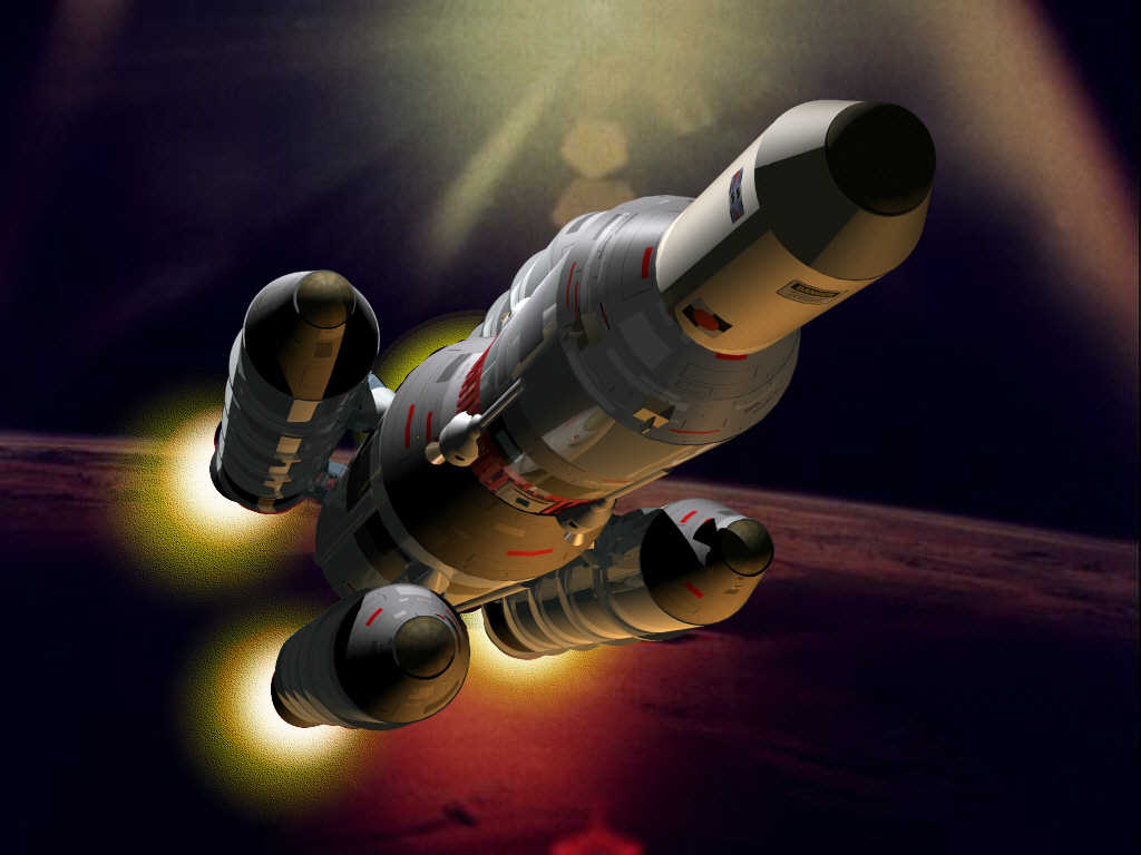 |
This
heavy space booster uses four strap-on solid-fuel rocket boosters
(SRBs) for its initial ascent to orbit. In this image, the SRBs are
near burnout. Thrust is tailing off, with no more than bright glow of
residual propellant combustion showing from the booster nozzles. The
empty cases are just about to be jettisoned. The core stage will soon
ignite and continue pushing the vehicle toward its orbital injection
point. The earth picture forming the background of this image was taken on one of NASA's manned missions. After rendering this scene in trueSpace 4, I added the glowing SRB exhaust plumes in MicroGrafx Picture Publisher 8. |
| SRB Separation | |
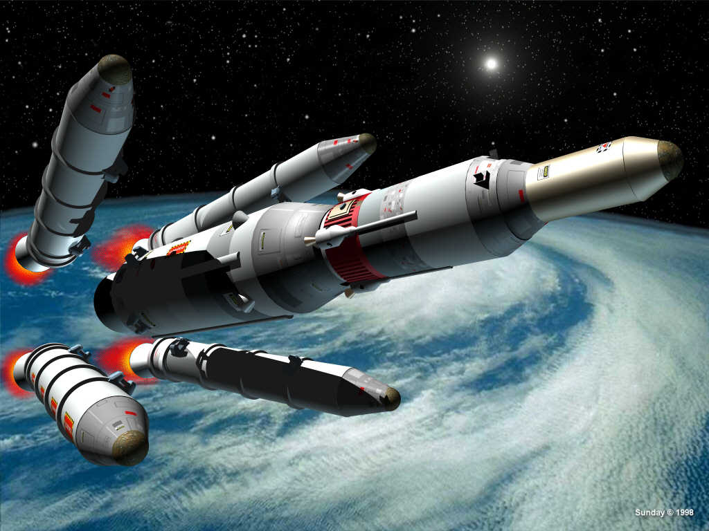 |
The four strap-on solid-fuel rocket boosters
(SRBs) of a heavy space launch vehicle have burned out and are dropping away from the core
stages, which will continue on to orbit. The configuration shown is similar to the Russian
SL-6 Soyuz-class
booster, the world's longest-serving rocket. First launched in 1957,
upgraded versions of it are still in use today (early 2015) as the only
way to transport crews to the International Space Station (ISS). This image was the runner-up winner in the Caligari Software February 2000 Image Contest at http://www.caligari.com/gallery/imagesgallery/2000/Feb00/index.html |
| Stage Two Ignition | |
 |
Here the second stage liquid-fuel engine is igniting just after the first stage burned out (note the red glow from the still-hot first stage nozzle). The four hinged panels of the inter-stage structure have pivoted back, freeing the second stage. The first-stage core will soon re-enter the atmosphere and burn up over the ocean. Note the attachment points for the discarded SRBs, and the pipes and valves of the thrust-vector control (TVC) system around the first stage nozzle. The second-stage nozzle ignition flash is a one-click lens flare effect from Corel PhotoPaint 8. |
| Encounter With The Giant | |
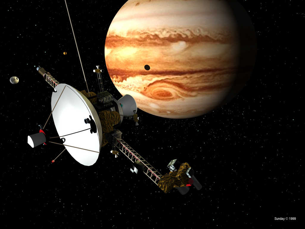 |
Here an unmanned interplanetary probe nears the giant planet Jupiter. The probe depicted is a "composite" design, combining features from several actual probes. A nuclear generator is on the left boom (solar cells are impractical at Jupiter's distance from the sun because the sunlight is too dim), balanced by an articulated instrument scan platform on the right boom. The trajectory-correction rocket nozzle protrudes from among gold-foil-wrapped electronics modules. The moons Io and Europa are visible, one casting its shadow on the planet. Jupiter's cloud formations and the moons' surfaces are based on downloaded image maps (see Links page). |
| Over The Red Spot | |
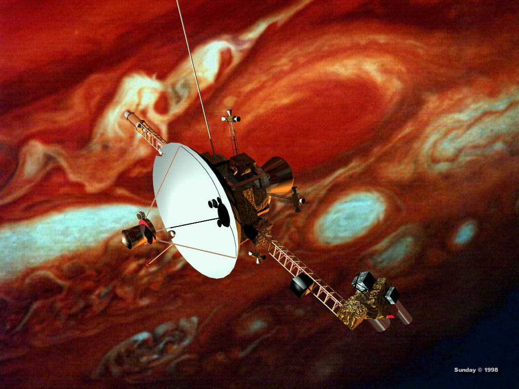 |
Here the interplanetary probe passes over the Great Red Spot, an enormous permanent storm in Jupiter's upper atmosphere that could swallow the earth without a trace. The background image is a NASA Voyager photograph, with the colors exaggerated to bring out the details in the cloud structure. The lighting on this image is distinctly reddish-yellow, reflecting the colors in the background image. |
| Shuttle Entering Orbit | |
 |
Among the Wernher von Braun/Chesley Bonestell 1953-vintage
spacecraft designs was a huge, three-stage winged cargo shuttle. Much more powerful than NASA's Saturn 5 moon rocket, the shuttle vehicle at takeoff would have measured 265 feet tall
and 65 feet in diameter at the base, not including its enormous fins. Its first-stage
thrust would have been an awesome 28 million pounds (the Saturn V produced 7.5 million pounds of thrust), generated by a cluster of 52 rocket engines.
This was aerospace engineering at its most grandiose. In fact, the configuration resembles the
abortive Soviet N-1 moon rocket, which clustered 30 engines in its first stage and had a
similar conical shape, and that failed dramatically in each of its four launch attempts. The massive von Braun/Bonestell shuttle was designed to carry components of the Space Station into orbit and to resupply the Station after it was completed. One of Bonestell's most famous paintings for Collier's was a view of the manned third stage of the shuttle separating from the second stage, which had just deployed a metallic parachute for its descent back to a soft landing on Earth. This image depicts the third stage at the end of its final orbit-insertion burn (note the glowing engine nozzles). |
| The "Space Wheel" | |
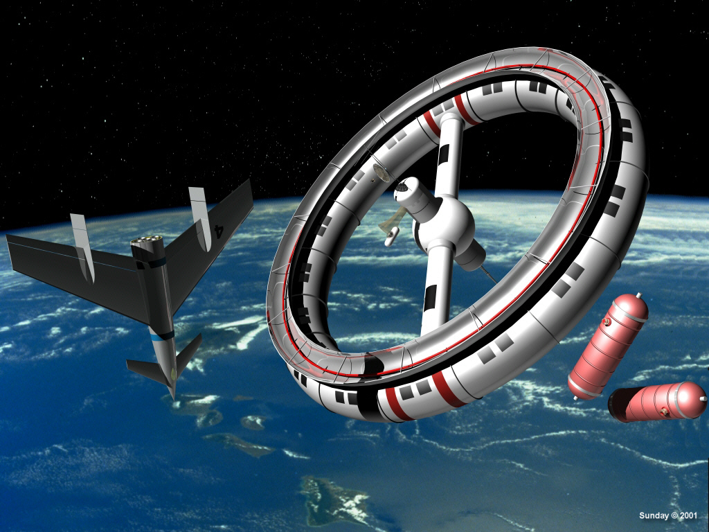 |
Von
Braun and Bonestell did not originate the concept of a wheel-shaped
Space Station spinning on its axis to create artificial gravity for its
crew. But they probably did more than anyone to popularize the idea.
Thanks to their efforts, many people today still automatically envision
a "Space Wheel" whenever they think about a space station. The
mind-numbingly complex, angular and frail-looking International Space
Station currently in orbit lacks the raw emotional appeal of a simple
wheel rotating majestically in silent splendor against the blackness of
deep space as the Earth passes by below. Would 2001,
A Space Odyssey have been the same movie if it had laceked the giant Space Wheel? Here a shuttle from Earth floats beside the Space Station, while some tanks slated for an ongoing construction project drift nearby. A small Space Taxi, perhaps carrying the shuttle crew, approaches one of the docking ports in the Space Station's non-rotating, zero-gravity hub. The red tube on "top" of the station carries mercury in a mirrored trough. Vaporized by reflected sunlight, the mercury vapor spins turbines to provide power to the station. Remember, solar cells had not yet been invented at the time this station was conceived. |
| Shuttle on Landing Approach | |
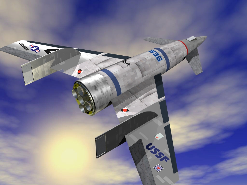 |
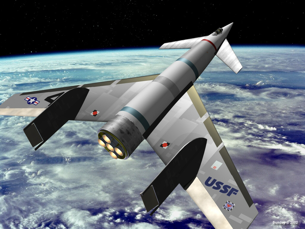
Wernher
von Braun's canard-configuration shuttle design, like NASA's actual
Space Shuttle, would have landed on a conventional airfield runway at
the end of its orbital mission. Here the von Braun Shuttle Columbia
turns onto final approach just before landing. I used Bryce 4 to create the sky background, modeled the shuttle in trueSpace 4.3 and then rendered the shuttle over the sky background image. NOTE: This image was done long before NASA's Space Shuttle Columbia tragically disintegrated while re-entering the Earth's atmosphere on February 1, 2003. |
| Cargo Ship Entering Orbit | |
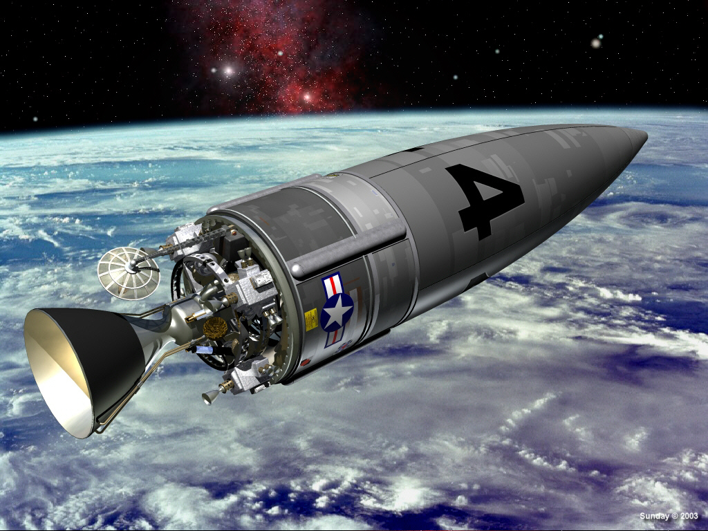 |
The unmanned cargo rocket was the mainstay of the great space program conceived by Wernher von Braun in the early 1950's. Construction of the giant wheel-shaped manned Space Station and, later, the three huge moonships, would require thousands of tons of building materials, consumable supplies and fuels. Thundering into space from a launch site on Johnston Island near the equator--to gain the most benefit from the speed of the Earth's rotation--these cargo ships keep busy constantly. All three stages are reusable; parachuting into the ocean after launch, they need only a ten-day refurbishment to be ready for the next launch. In this image, the third stage coasts in space just before its engine ignites. The first and second stages have burned out and dropped away, leaving this stage as the only part of the ship to reach orbit. This is the dry cargo version--von Braun also designed a somewhat longer tanker version for carrying liquids. |
| Cargo Ship Shroud Separation | |
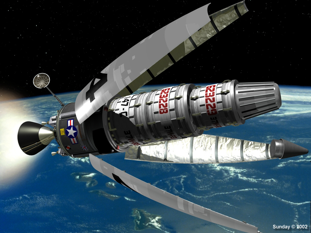 |
After its third-stage engine ignites, the unmanned cargo rocket sheds the protective fairing that shields its cargo modules from atmospheric friction on its way into orbit. The covering on the inner surfaces of the fairing petals is gold multi-layer insulation (MLI) to further control heat transfer during ascent. Each of the three cargo modules carries a coded number to aid space-suited workers in unloading and sequencing them at the Space Station. The mesh antenna near the rocket nozzle points at a relay satellite, receiving data transmitted from the Space Station to control the cutoff time of the engine. This will improve the accuracy of the initial orbit. The four small engine clusters around the base control the ship's attitude, and make any trim burns needed for the ship to match the Space Station's orbit exactly. |
| Von Braun-Bonestell Passenger Moonship - 1 | |
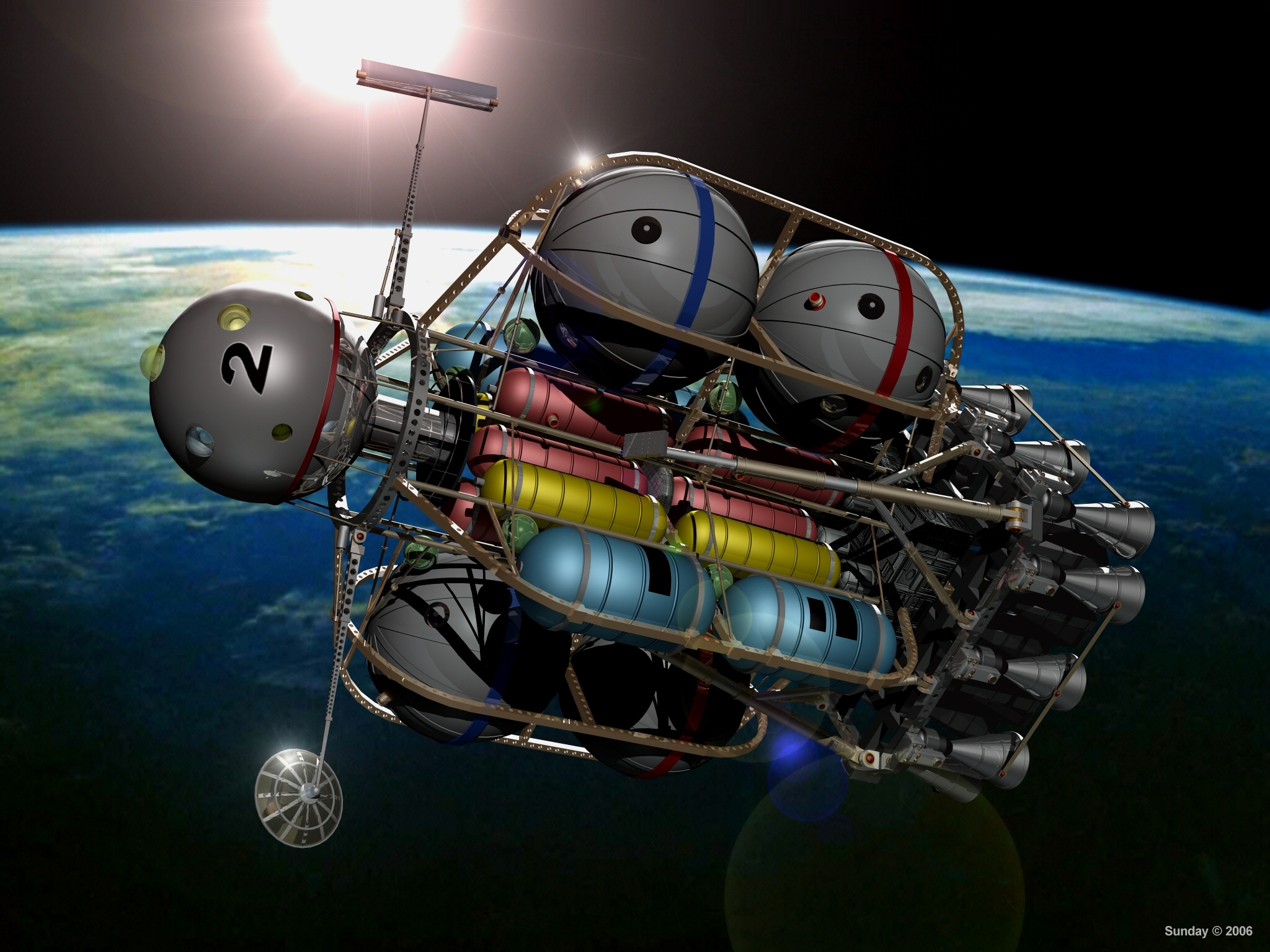 |
In the early 1950s, Wernher von Braun envisioned a massive space program that, in retrospect, no
single nation on Earth could have afforded. His lunar exploration program featured a fleet of
three enormous moonships, built in low Earth orbit near the giant wheel-shaped Space
Station. Here's one of the huge moonships in orbit. They would never have entered the earth's atmosphere, so streamlining was unnecessary. Von Braun designed these ships before the invention of Multi-Layer Insulation (MLI), the gold foil that covers spacecraft today. A combination of paint, polished and matte metallic surfaces and adjustable louvers (the black circles seen here on some of the spherical tanks) would have controlled the temperatures of the tanks and crew sphere. This image appears in "Space 50" by Piers Bizony (Collins/Smithsonian Books, 2006). You can find it at www.amazon.com or bookstores everywhere.
|
| Von Braun-Bonestell Passenger Moonship - 2 | |
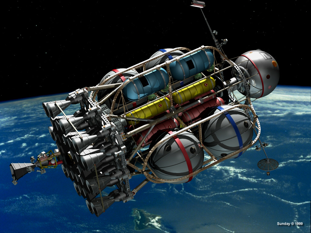 |
Space-suited workers change an engine on one of
the passenger moonships as it passes 1,075 miles over the Hawaiian Islands. The 18
hex-shaped engines in the central cluster are fixed. The 12 outer engines swivel to
control the ships attitude during burns. Solar cells didn't exist in 1953, when von
Braun designed these ships. For electrical power, a mirror (seen here on the strut to the
left of the crew sphere) focuses sunlight on a tube filled with liquid mercury, which
vaporizes and spin a turbine generator. The other strut mounts a communications antenna. This image won an honorable mention in the Caligari Software February 2000 Image Contest at http://www.caligari.com/gallery/imagesgallery/2000/Feb00/index.html |
| Moonship Fleet in Earth Orbit | |
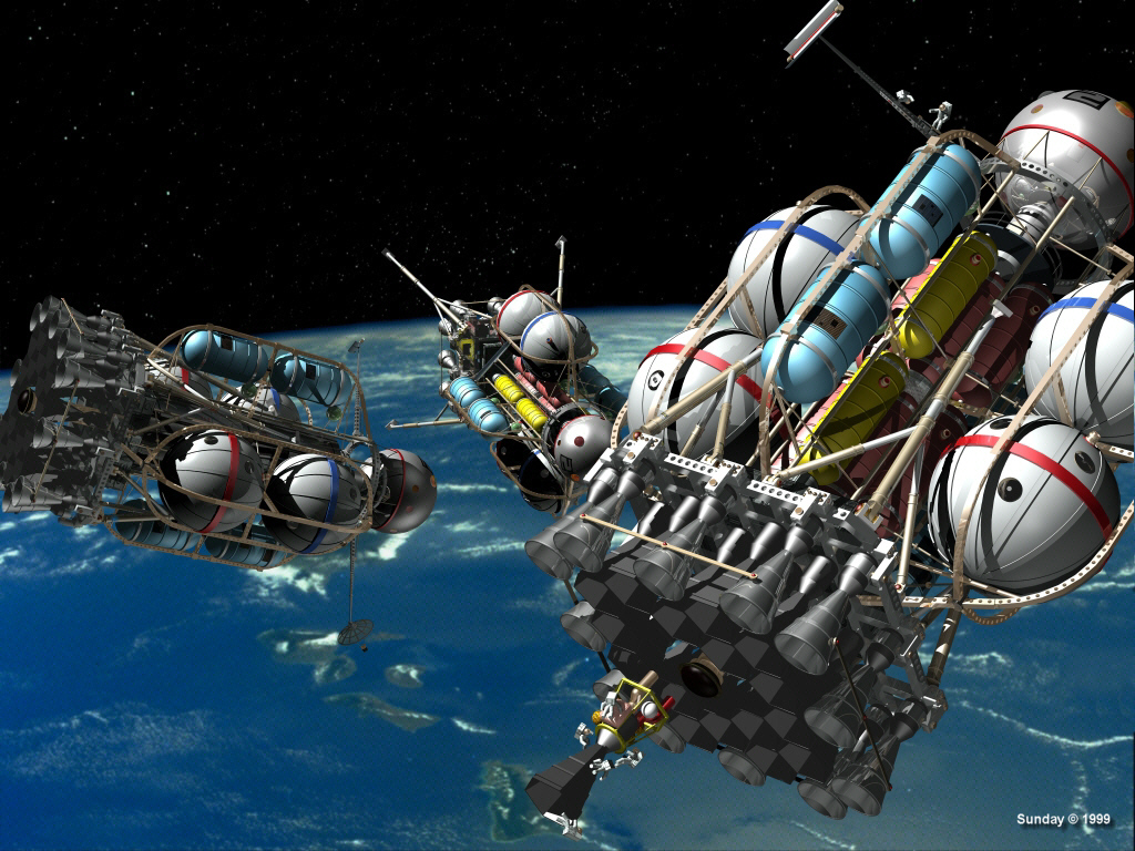 |
The
three moonships undergo final checks before they leave for the moon.
The four spherical white tanks on each ship contain fuel and oxidizer
for the outbound trip. They are discarded after Trans-Lunar Injection
(TLI). The cylindrical blue tanks contain the propellants used for
landing. They're left on the moon. The yellow and red tanks on the two
passenger ships contain the propellants to return the ships to Earth
orbit and rendezvous with the Space Station. The cargo ship on the
left, which will stay on the moon, carries a cargo pod instead of
earth-return tanks. This image deliberately resembles a magnificent Chesley Bonestell painting originally published in 1953 in the book Conquest of the Moon. |
| Midcourse Correction | |
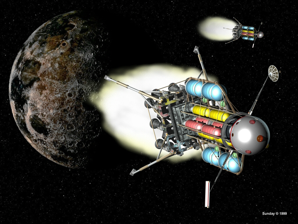 |
Brief midcourse-correction engine burns adjust
the trajectories of two of the three ships of the moonward-bound fleet. The white
spherical departure tanks are gone, discarded after the ships left low Earth orbit. The image of the moon here is from an unknown Internet source. Its colors are all wrong--the moon is not brown and tan. If I were to do this scene again, instead of a background picture of the moon I would place a sphere mapped with real lunar texture and bump maps into the scene. The engine exhaust plumes were the hardest part of creating this image. After trying several techniques, I ended up painting them on the background in Micrografx Picture Publisher and then rendering the ships over the plumes. |
| Passenger Moonship Landing | |
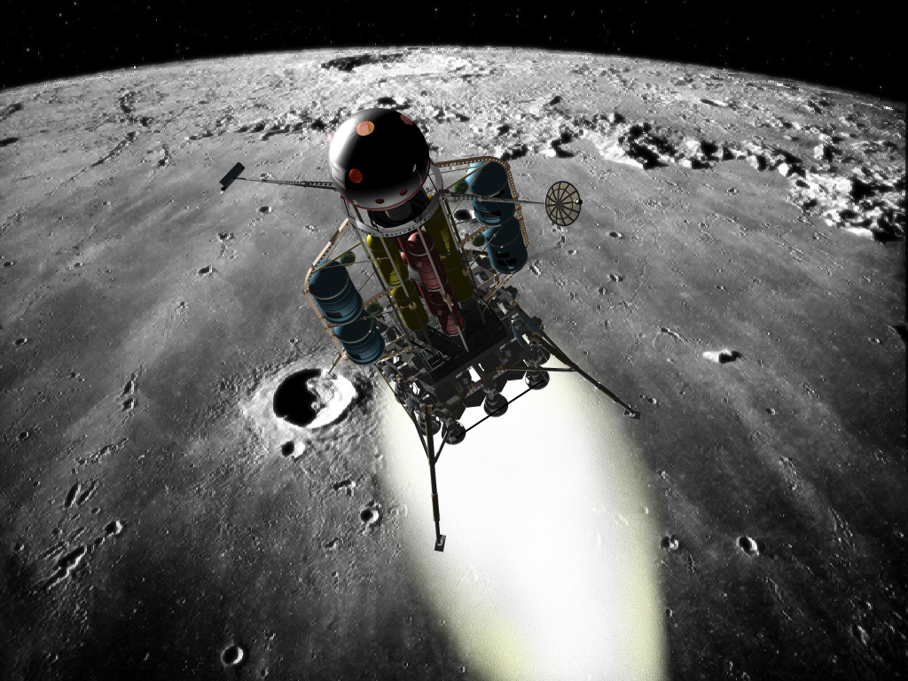 |
A passenger moonship, all engines burning and
landing legs extended, swings low over the moon on course for touchdown. The lunar surface here is a photograph from one of the Apollo missions. I retouched it to remove an experiment boom that stuck into the picture from the right. I then pasted the lunar surface photo over a star-studded background image. Again, I painted the exhaust plume onto the background using Picture Publisher, and then rendered the ship over the flame. |
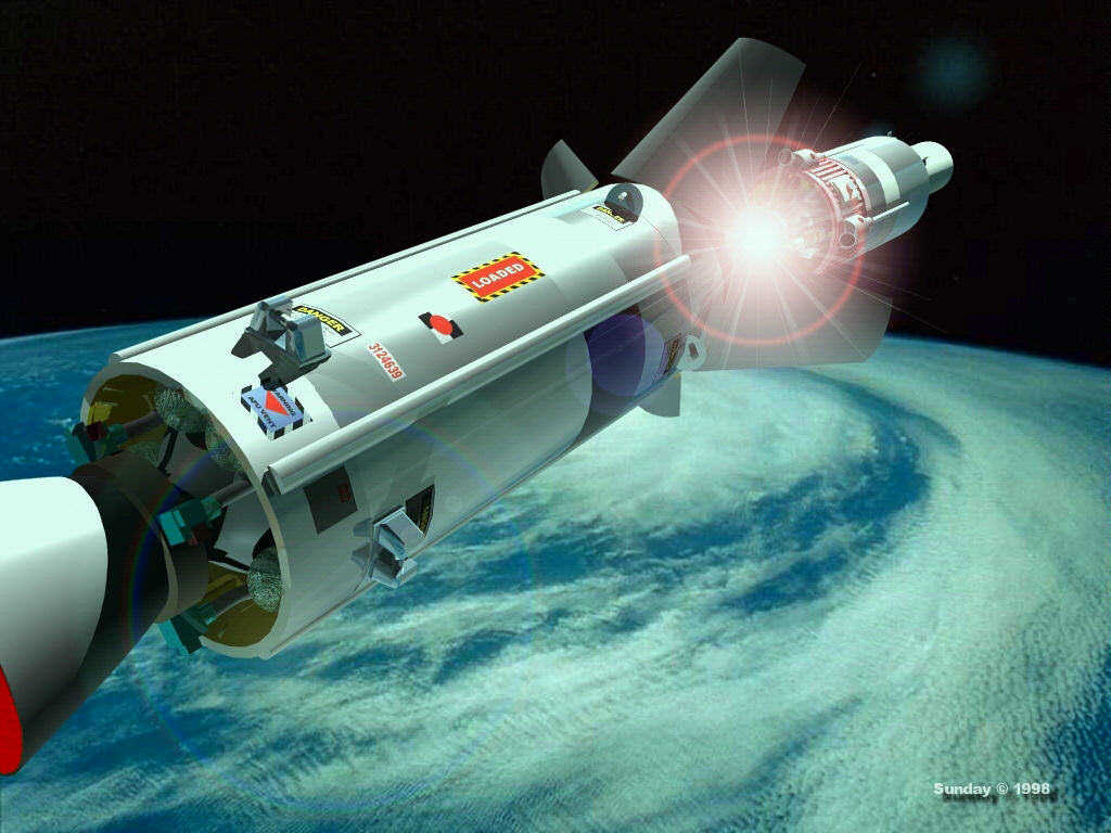
| Lunar Missile Weapon Launch | |
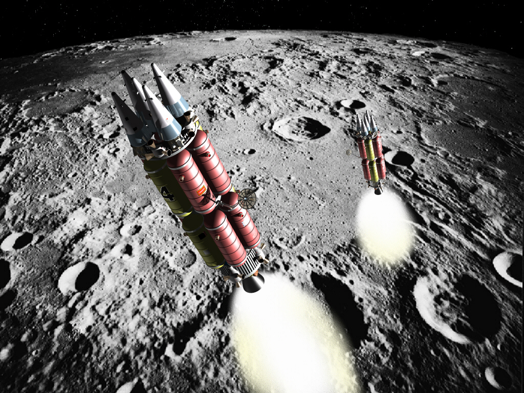 |
Early in the Space Age, some American military "experts" feared the
Soviet Union would station nuclear missiles on the moon and hold the nation (or the whole
Earth) hostage. The fear was not well-founded. "Missiles on the moon" was a spectacularly dumb idea. They would have been expensive, inefficient and inaccurate. With more than two days warning between missile launch and arrival at Earth, there would have been plenty of time for the target nation to take defensive measures or launch a devastating counterstrike on the aggressor. But let's imagine for a moment the moon were a military missile base. Here's what an "interplanetary ballistic missile" might look like. These 15-megabyte models are made up of bits and pieces from other models. The tanks and antenna come from the passenger moonship, the engine is from the booster upper stage and the five independently targetable nuclear warheads are modified "baby satellites." The background is a retouched NASA Apollo photo. |
| Lunar Missile Weapon Warhead Release | |
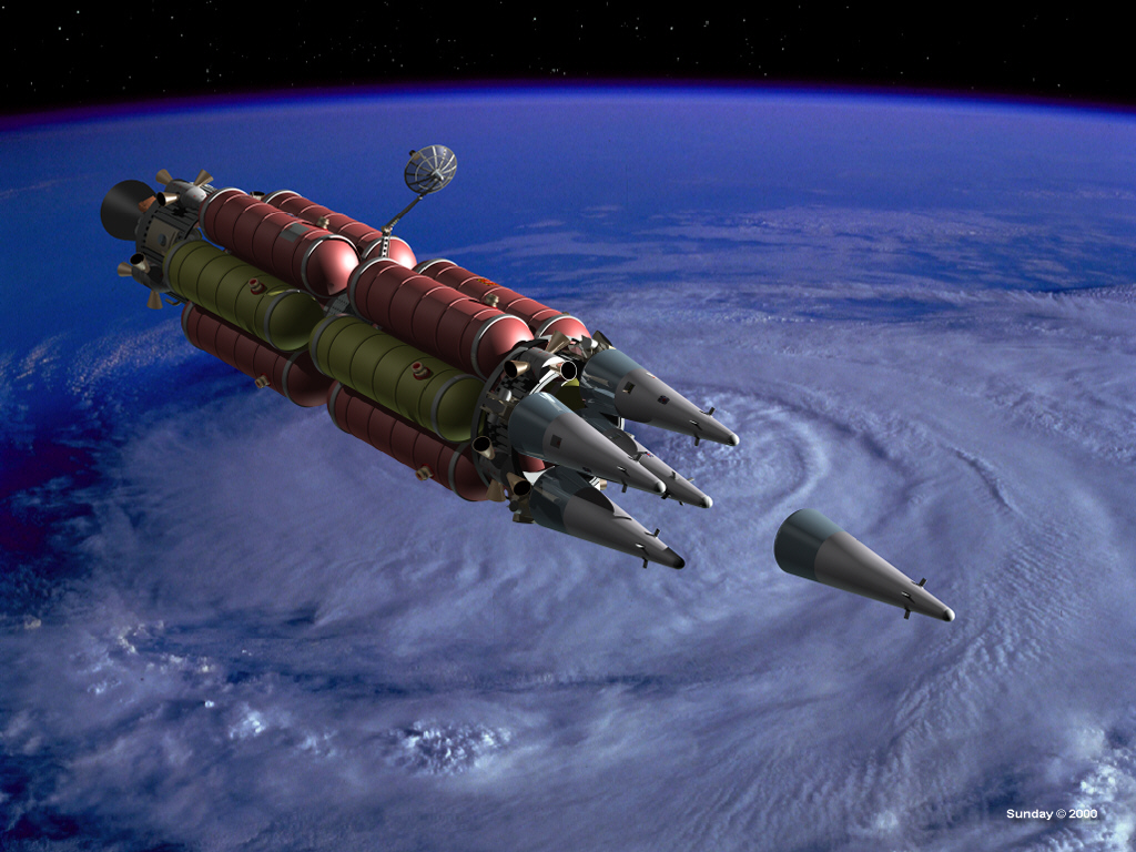 |
Okay,
so it's a dumb idea. But just for grins, let's say a lunar-based
"interplanetary ballistic missile" is launched--target: Earth. After a
two-day coast period, the vehicle approaches at a speed of 25,000 miles per hour. It's a MIRV missile, carrying
five multiple independently-targetable reentry vehicles. As each RV
warhead is released, the "bus" maneuvers to a different attitude and
velocity vector for the next release. This technique can place all five
RVs (or, to be precise in this case, "entry" vehicles, or "EVs") on
separate targets. Here's what such an operation might look like. One warhead has just been released, and the others will follow in quick succession to detonate in multi-megaton air bursts above cities or military installations. |
| Thermonuclear Weapon Cutaway | |
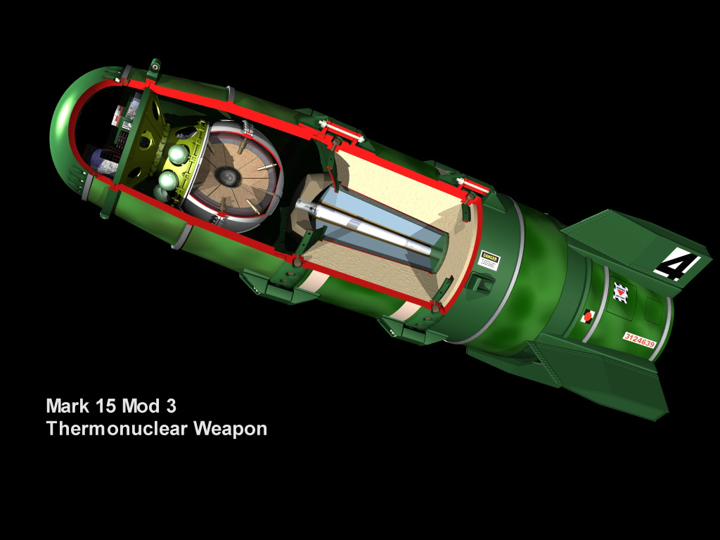 |
Nuclear
weapons have always fascinated me. As an engineer, I appreciate clever
solutions to difficult problems, and I enjoy studying elegant,
functional designs. From what I've learned reading the literature (I
have no special knowledge beyond what's available to the general
public), nuclear weapons are an engineer's dream--as Dr. Robert
Oppenheimer, head of the Manhattan Project that developed the world's
first atomic bomb, allegedly once said, they're "technically sweet." This depiction of a two-stage thermonuclear "device" is totally conjectural. I have no idea whether it's accurate or not, but it showcases well trueSpace's ability to handle complex technical objects. My objective was to translate general physical principles, and descriptions that I found in many books and on-line sources, into a realistic-looking nuts-and-bolts object. I imagined the details of how such a weapon might be designed, assembled, serviced, transported and tested, and tried to make the model reflect sound engineering judgments based on my long career as an aerospace engineer. The fission trigger primary stage is the sphere in the nose, and the secondary lithium
deuteride thermonuclear or "hydrogen" component is the tapered cylinder behind
the primary. "Radiation implosion," a concept invented by physicists Drs. Edward Teller and
Stanislaw Ulam, purportedly is the method by which the explosion of the fission primary
ignites the secondary. Google "Teller-Ulam configuration" and you'll be amazed at what pops up. "Mark 15 Mod 3" was not the designation for a real U.S. thermonuclear gravity bomb (as far as I know). Eventually I plan to put this model in a museum scene based on the National Atomic Museum in Albuquerque, New Mexico. |
| Sprint Anti-Ballistic Missile | |
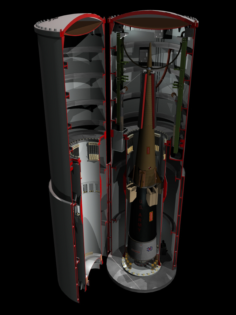 |
In the 1970s, the Martin Marietta Corporation (now
Lockheed Martin) in Orlando, Florida, built what is still today one of the most incredible
guided missiles ever to fly. Sprint was a part of the only anti-ballistic missile (ABM) system that the United States ever deployed. It complemented the long-range Spartan interceptor, which was intended to destroy incoming nuclear warheads before they re-entered the atmosphere. Sprint was a short-range, close-in screamer with literally split-second reaction times. It could intercept any warheads that got past Spartan when they were only seconds from their targets. Ejected from an underground silo by a hot gas generator, the two-stage Sprint accelerated so fast that it would pass a .50-calibre bullet, if fired at the same time, within a second. Atmospheric friction made the outer skin of the second stage hotter than the searing flame inside the rocket motor. The skin was protected by a thick ablative layer that actually boiled away, carrying most of the heat with it. Sprint was tested successfully many times at White Sands Missile Range, New Mexico and against actual re-entering (dummy) warheads at the Kwajalein Missile Range in the Pacific. It was beyond-state-of-the-art technology for its day. This image shows Sprint in its silo. The missile sits on the eject piston, which in turn rests on a ring of springs to cushion the missile from ground shocks due to nearby nuclear explosions. When the gas generator under the piston fires, the piston shoots up the launch tube (stopping when it hits the piston arrestors at the tube mouth) and the Sprint continues out of the cell, literally blasting through the frangible fiberglass, foam and rubber domed cell closure. Tan "wedges" at the missile's midsection near the second stage fins guide it out the tube. The cutaway shroud near the top of the missile is the "foam sock," an insulating blanket around the guidance section and warhead that keeps the components at operating temperature at all times. |
| Re-Entry Vehicle Cutaway | |
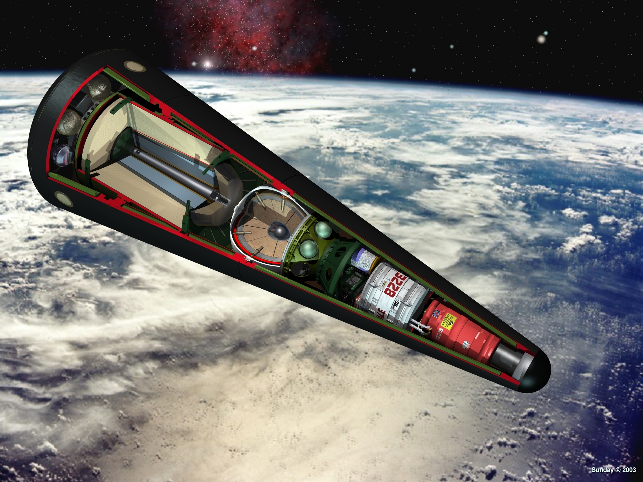 |
Here's another example of trueSpace's
ability to handle detailed "nuts-and-bolts" objects. The re-entry vehicle
contains the same primary-secondary thermonuclear fission-fusion "physics
package" as seen in the gravity bomb
image. Around the base of the RV are pressurized spheres containing
propellant for the attitude control and spin-up rocket engines. The
light-colored object in front of the primary is the adaption kit
containing the warhead's safing, arming and fusing circuits. The red
object in the RV's nose is the inertial measurement and guidance unit
which continuously calculates the position and motion of the RV in
space in order to trigger warhead detonation at the optimum point above
the ground over its target. DISCLAIMER: Of course, all of these pieces of hardware and their functions are purely conjectural. |
| Galaxy Planets | |
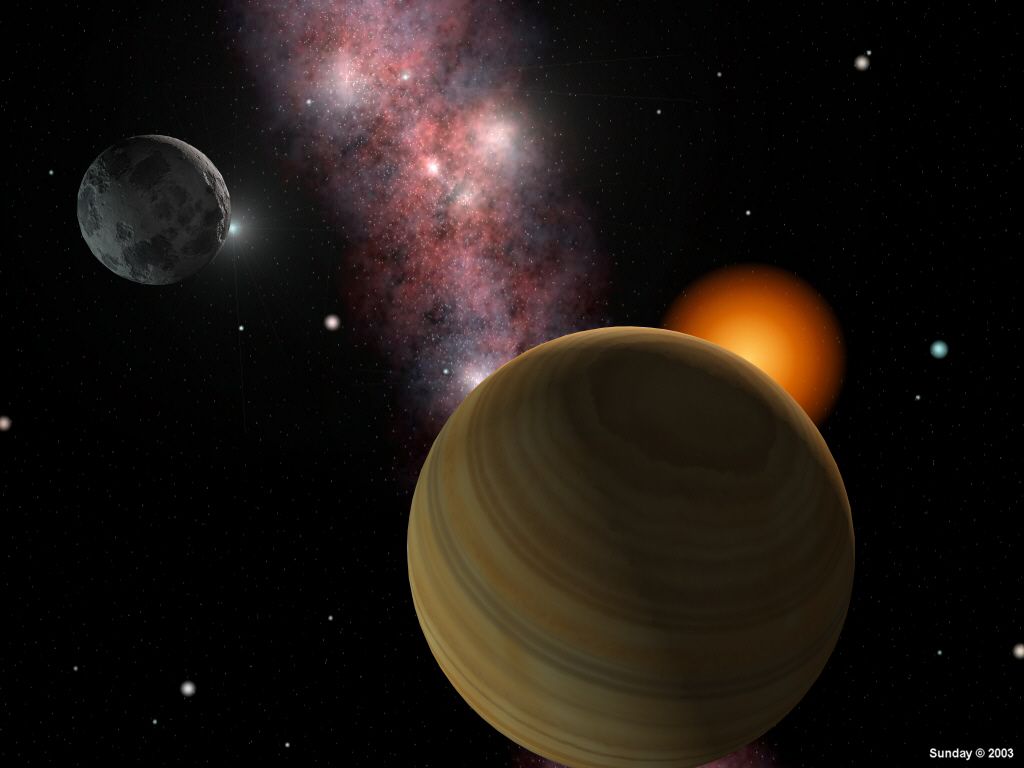 |
This image is an experiment in the use of Darkling Simulation's DarkTree Textures software. A
top-of-the-line program that can generate some incredible procedural textures for use in
3D rendering software, DarkTree Textures has a fairly steep learning curve, but it
produces results that are well worth the effort required to master it. I used DarkTree to create the galactic gas and dust clouds in this image. I added the orange-giant sun and some bright stars in Corel PhotoPaint Version 8, then used the resulting image as the background behind two planets (also textured with DarkTrees) rendered in trueSpace 4.3. All in all, I'm happy with the result. The next step will be to develop DarkTrees for creating detailed terrestrial planets with oceans, land masses and clouds, and a variety of barren moons of different compositions. |
Comments? Compliments? Complaints? Commissions?

Copyright � 1998 - 2015 by Terry L. Sunday.
All rights reserved. Please ask permission before using any of these images for any
reason.
Some of the background images for these works are available in the public domain.