The Sparks Telegraph Key Review
Engineering Blueprints and Drawings, Transmitter Manuals, & Company Catalogs
A list of original research material on file at the Sparks Telegraph Key Review
- Kilbourne & Clark Mfg. Co. antenna switch Type SE-165 1918 KS-983 (8-1/2" x 11" single sheet)
- Kilbourne & Clark Mfg. Co. antenna transfer switch 1916 KN-705 full size (sheet 1 of 7)
- Kilbourne & Clark Mfg. Co. antenna transfer switch 1916 KN-705 full size (sheet 2 of 7)
- Kilbourne & Clark Mfg. Co. antenna transfer switch 1916 KN-705 full size (sheet 3 of 7)
- Kilbourne & Clark Mfg. Co. antenna transfer switch 1916 KN-705 full size (sheet 4 of 7)
- Kilbourne & Clark Mfg. Co. antenna transfer switch 1916 KN-705 full size (sheet 5 of 7)
- Mach'y Div U.S. Navy Yard, NY Antenna Switch Type "F" 1913 full size sheet (sheet 1 of 4)
- Mach'y Div U.S. Navy Yard, NY Antenna Switch Type "F" 1913 full size sheet (sheet 2 of 4)
- Mach'y Div U.S. Navy Yard, NY Antenna Switch Type "F" 1913 full size sheet (sheet 3 of 4)
- Mach'y Div U.S. Navy Yard, NY Antenna Switch Type "F" 1913 full size sheet (sheet 4 of 4)
- Mach'y Div U.S. Navy Yard, NY Antenna Switch Type "H" 1915 full size sheet (sheet 1 of 5)
- Mach'y Div U.S. Navy Yard, NY Antenna Switch Type "H" 1915 full size sheet (sheet 2 of 5)
- Mach'y Div U.S. Navy Yard, NY Antenna Switch Type "H" 1915 full size sheet (sheet 3 of 5)
- Mach'y Div U.S. Navy Yard, NY Antenna Switch Type "H" 1915 full size sheet (sheet 4 of 5)
- Mach'y Div U.S. Navy Yard, NY Antenna Switch Type "H" 1915 full size sheet (sheet 5 of 5)
- Kilbourne & Clark Mfg. Co. antenna transfer switch KM 773 for 5 KW Simpson Radio Transmitter 1916 full size sheet (sheet 1 of 2)
- Kilbourne & Clark Mfg. Co. antenna switch KM 567 1914 full size sheet (sheet 1 of 1) [blueprint]
- Kilbourne & Clark Mfg. Co. antenna switch KM 567 1914 full size sheet (sheet 1 of 1) [duplicate on onionskin]
- Kilbourne & Clark Mfg. Co. Hand Key for 1-2-5 KW KM-903 1917 full size sheet (sheet 1 of 1)
- Kilbourne & Clark Mfg. Co. Type A Relay Key Back Connected Assembly 1913 KN-317 full size sheet (sheet 1 of 2)
- Kilbourne & Clark Mfg. Co. Type A Relay Key Back Connected Assembly 1913 KN-317 full size sheet (sheet 2 of 2)
- Kilbourne & Clark Mfg. Co. Type A Relay Key Front Connected Assembly 1913 KN-316 full size sheet (sheet 1 of 2)
- Kilbourne & Clark Mfg. Co. Type A Relay Key Front Connected Assembly 1913 KN-316 full size sheet (sheet 2 of 2)
- Kilbourne & Clark Mfg. Co. Type A Relay Key 1914 KN-386 full size sheet (sheet 2 of 2)
- Kilbourne & Clark Mfg. Co. Type A Relay Key 1916 KN-698 full size sheet (sheet 1 of 1)
- Kilbourne & Clark Mfg. Co. Wireless Key 1 to 5 KW 1911 JN-204 mid size sheet (sheet 1 of 1)
- Kilbourne & Clark Mfg. Co. Hand Key for 20 KW Simpson Transmitter KM-800 1916 full size brown paper sheet (sheet 1 of 1)
- Kilbourne & Clark Mfg. Co. Hand Key KN-802 1917 full size sheet (sheet 1 of 1)
- Kilbourne & Clark Mfg. Co. Main Key 5 KW KN-390 1914 full size sheet (sheet 1 of 1)
- Kilbourne & Clark Mfg. Co. Hand Key KN-563 1914 full size sheet (sheet 1 of 1)
- Kilbourne & Clark Mfg. Co. 2 KW Hand Key KN-1055 1918 full size sheet (sheet 1 of 1)
- Kilbourne & Clark Mfg. Co. Hand Key KN-802 1917 full size sheet (sheet 1 of 1)
- Kilbourne & Clark Mfg. Co. 1/2 KW Flame Proof Hand Key Simon Design KR-1069 1918 mid size sheet (sheet 1 of 1)
- Lowenstein (Signal Corps U.S. Army) Type C.B. Contacts for 10 KW Radio Sending Key 1917 mid size sheet (sheet 1 of 1)
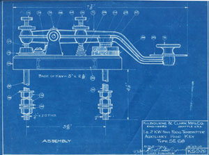
- Kilbourne & Clark Mfg. Co. 1 & 2 KW Auxiliary Hand Key Type SE-68 1917 (sheet 1 of 3)
- Radio Division BuSE Navy Dept. Washington D.C. Radio Telegraph Motor Buzzer Type SE-3558 (110V) & SE-3629 (220V) 1918 full size sheets (sheet 1 of 5)
- Radio Division BuSE Navy Dept. Washington D.C. Radio Telegraph Motor Buzzer Type SE-3558 (110V) & SE-3629 (220V) 1918 full size sheets (sheet 2 of 5)
- Radio Division BuSE Navy Dept. Washington D.C. Radio Telegraph Motor Buzzer Type SE-3558 (110V) & SE-3629 (220V) 1918 full size sheets (sheet 3 of 5)
- Radio Division BuSE Navy Dept. Washington D.C. Radio Telegraph Motor Buzzer Type SE-3558 (110V) & SE-3629 (220V) 1918 full size sheets (sheet 4 of 5)
- Radio Division BuSE Navy Dept. Washington D.C. Radio Telegraph Motor Buzzer Type SE-3558 (110V) & SE-3629 (220V) 1918 full size sheets (sheet 5 of 5)
- Radio Division BuSE Navy Dept. Washington D.C. Impedance Type SE-3559A Assembly 1919 full size sheets (sheet 1 of 4)
- Radio Division BuSE Navy Dept. Washington D.C. Impedance Type SE-3559A Assembly 1919 full size sheets (sheet 2 of 4)
- Radio Division BuSE Navy Dept. Washington D.C. Impedance Type SE-3559A Assembly 1919 full size sheets (sheet 3 of 4)
- Radio Division BuSE Navy Dept. Washington D.C. Impedance Type SE-3559A Assembly 1919 full size sheets (sheet 4 of 4)
- Radio Division BuSE Navy Dept. Washington D.C. Stand For Motor Buzzer Sets 1918 full size sheet (sheet 1 of 1)
- Radio Division BuSE Navy Dept. Washington D.C. Booth Protecting Relay 1919 full size sheet (sheet 1 of 9)
- Radio Division BuSE Navy Dept. Washington D.C. Schematic Wiring Diagram of Type SE-3558 & 3629 Motor Buzzer Transmitters 1919
mid size sheet (sheet 1 of 1)
- Federal Telegraph Coompany, Instructions for Models "K" & "Q" 2 KW Arc Radio Transmitters 1919, including drawings & photos 8"x11" for:
- Outline 2 KW Arc Converter Type CT-1461 1919
- Outline 2 KW Arc Converter Type CT-1461 and Water Pump 1919
- Outline of Anode Insulating Disc and Gasket Type CT-1464 2 KW Arc Converter 1919
- Outline of Anode Tip and Gasket Type CT-1463 2 KW Arc Converter 1919
- Outline of Carbon Electrode Type CT-1466 2 KW Arc Converter 1919
- Water Circulation Diagram 2 KW Arc Converter 1919
- Outline of Antenna Loading Inductor Type CT-1470 2 KW Arc Converter 1919
- Outline of Variometer Type CT-1479 2 KW Arc Converter 1919
- Outline of Send-Ground Receive Switch Type CT-1475 2 KW Arc Converter 1919
- Outline of Back Shunt Relay Key Type CT-1471 2 KW Arc Converter 1919
- Outline of Chopper Type CT-1476 2 KW Arc Converter 1919
- Outline of Auxiliary Hand Key & Contact Type CT-1474 & Contact SE-507 2 KW Arc Converter 1919
- Outline of Morse Hand Key Type CT-1576 & Contact SE-505 2 KW Arc Converter 1919
- Outline of Chopper Transfer Switch 2 KW Arc Converter 1919
- Outline of Back Shunt Circuit Type CT-1472 2 KW Arc Converter 1919
- Outline of Cooling Water Tank Type CT-1467 2 KW Arc Converter 1919
- Outline of Centrifugal Pump Type CT-1468 2 KW Arc Converter 1919
- Outline of Radio Frequency Ammeter Panel Type CT-1477 2 KW Arc Converter 1919
- Outline of Series antenna condenser Type CT-1494 2 KW Arc Converter 1919
- Outline of Pressure Regulator for 2 KW Arc Converter 1919
- Outline of Low Power Resistor Type CT-1478 2 KW Arc Converter 1919
- Outline of Spare Parts Boxes Models Q, K, X 2 KW Arc Converter 1919
- Wiring Diagram 2 KW Arc Converter 1919
- Wiring Diagram Hand Starting Panel 2 KW Arc Converter 1919
- Outline of Arc Control Panel Type CT-1469 2 KW Arc Converter 1919
- Outline of Motor Generator Type CB-1438 2 KW Arc Converter 1919
- Outline of Hand Starting Panel 2 KW Arc Converter 1919
- Outline of Generator Field Rheostat 2 KW Arc Converter 1919
- Lowenstein Radio Co., Index Sheet for 5 KW Quench Spark Gap Radio Sets, 1916, including drawings 8"x11" (except where indicated) for:
- Switchboard Type K 2 & 5 KW Radio Set F. Lowenstein
- DC Automatic Starter Type Indust. Control Co. 5 KW Radio Set F. Lowenstein
- Transfer Switch Panel Type-Cutler Hammer 5 KW Radio Set F. Lowenstein
- DC Hand Starter Type Indust. Control Co. 5 KW Radio Set F. Lowenstein
- Dimensions Crocker Wheeler Motor Generator furnished by F. Lowenstein with 5 KW Radio Set
- Assembly Crocker Wheeler Motor Generator furnished by F. Lowenstein with 5 KW Radio Set
- Connection Diagram Crocker Wheeler Motor Generator furnished by F. Lowenstein with 5 KW Radio Set
- Motor Gen. Protec Device Type N.Y.P. Style #1 2 & 5 KW Radio Set F. Lowenstein
- Motor-Generator Spare part box 5 KW Radio Set F. Lowenstein
- Relay Sending Key Type "B" 2 & 5 KW Radio Set F. Lowenstein
- Hand Sending Key Type "A" 2 & 5 KW Radio Set F. Lowenstein
- 5 KW 500 cycle radio transformer Type-AM Transform. Co. F. Lowenstein
- Transform. Protec. Device Type N.Y.P. Style #2 2 & 5 KW Radio Set F. Lowenstein
- Quenched Spark Gap Type A-16-G 5 KW Radio Set F. Lowenstein
- Quenched Spark Gap Tubular Unit Type G 2 & 5 KW Radio Set F. Lowenstein
- Directions for disassembling Spark Gap Unit Types F; G; Radio Set F. Lowenstein
- Directions for Assembling Spark Gap Unit Types F; G; Radio Set F. Lowenstein
- 4 Unit Rack for Dubilier Con Type P116 M.F. 004 2 & 5 KW Radio Set F. Lowenstein
- Antenna Switch Type H 2 & 5 KW Radio Set F. Lowenstein
- Lightning Switch Type H 5 KW Radio Set F. Lowenstein
- Aerial Ammeter Weston Model-400 Type 3 5 KW Radio Set F. Lowenstein
- Miscellaneous Spare Part Box 2 & 5 KW Radio Set F. Lowenstein
- Unit Assembly full-sized drawing 5 KW Radio Set F. Lowenstein
- Kilbourne & Clark Mfg. Co., U.S. Navy 1/2 KW Radio Transmitter Type CE 606A Manual, 1917, including drawings/photos 8"x11" (except where indicated) for:
- Fish Paper Gasket KS-942, Details of Spare Parts 1/2 KW Navy Radio Transmitter
- Locking Device & Shaft, KS-942, Details of Spare Parts 1/2 KW Navy Radio Transmitter
- Inner Contact Arm, KS-942, Details of Spare Parts 1/2 KW Navy Radio Transmitter
- Electrose Bushing with Lock Ring, KS-942, Details of Spare Parts 1/2 KW Navy Radio Transmitter
- Contact Arm, KS-942, Details of Spare Parts 1/2 KW Navy Radio Transmitter
- Plunger for Wave Changer, KS-942, Details of Spare Parts 1/2 KW Navy Radio Transmitter
- Rod Supports (Secondary Contactor), KS-942, Details of Spare Parts 1/2 KW Navy Radio Transmitter
- Contact, KS-942, Details of Spare Parts 1/2 KW Navy Radio Transmitter
- 1/2 KW 500 cycle Motor Generator Type G, KS-942 1/2 KW Navy Radio Transmitter
- 1/2 KW 500 cycle Motor Generator Type G, KS-942 1/2 KW Navy Radio Transmitter (outside view)
- Connection Diagram 1/2 KW 500 cycle Motor Generator Type G, KS-942 1/2 KW Navy Radio Transmitter
- Kilbourne & Clark Mfg. Co., U.S. Navy 1 KW Radio Transmitter Manual Type CK 621, 1917, including drawings/photos 8"x11" (except where indicated) for:
- 1-KW DC Motor Driven Naval Auxiliary Transmitter Wiring Diagram (large foldout page), HS 988A
- 1 & 2 KW Radio Transmitter Power Panel Schematic Wiring Diagram, HS 985
- Actual Wiring Diagram for 1 & 2 KW Radio Telegraph Power Panel (large foldout page), HS 1041
- The Electric Controller & Mfg. Co., 2 KW Auto Motor Starter, Type No. C.E.C. 206
- Connection Diagram Type CB 235 & 232 Crocker Wheeler
- Assembly & Connections 1 KW Navy Type Radio Transformer Type Cat.517, KS 1040
- Assembly Crocker Wheeler Motor Generator
- Dimensions Crocker Wheeler CB 232 Motor Generator
- 1 KW Navy Radio Transmitter Motor Generator Details of Brushholder, DS 1057, Sheet 1 of 2
- 1 KW Navy Radio Transmitter Motor Generator Details of Brushholder, DS 1057, Sheet 2 of 2
- The Electric Controller & Mfg. Co., Type A Series Magnetic Contactor
- 1 KW Navy Radio Room Panel Automatic Starter Contacts, ES 941
- 1 & 2 KW Navy Radio Transmitter Carbon Contacts for Double & Single Pole Circuit Breaker, ES 941
- 1 & 2 KW Navy Radio Transmitter Copper Contact for Single & Double Pole Clapper Switches, ES 941
- 1 & 2 KW Navy Radio Transmitter Starting Resistance Terminal, ES 1033, sheet 1 of 2
- 1 & 2 KW Navy Radio Transmitter Starting Resistance Terminal, ES 1033, sheet 2 of 2
- 1 & 2 KW Navy Radio Transmitter Auxiliary Hand Key Type SE-68, KS-926
- 1 & 2 KW Navy Radio Transmitter Hand Key Knob, KS-926
- 1 & 2 KW Navy Radio Transmitter Contact (details of spare parts), KS-926
- 1-KW Navy Radio Transmitter Quenched Spark Gap Assembly, KS-927
- 1-KW Navy Radio Transmitter Quenched Spark Gap Details, KS-927
- 1 & 2 KW Navy Radio Transmitter Details of Spark Gap, KS-927
- 1-KW Navy Radio Transmitter Details (bolt for spark gap), KS-927
- 1-KW Navy Radio Transformer, KS-925
- 1 & 2 KW Navy Radio Transmitter Dimensions of .004 MF Mica Condenser, KS-922
- 1 & 2 KW Navy Radio Transmitter Dimensions of protective device, KS-934
- 1 & 2 KW Navy Radio Transmitter Antenna Send-Receive Switch, Type L, Made by Marconi Wireless Telegraph Co., KS-983
- 1 & 2 KW Navy Radio Transmitter Drilling for Radio Frequency Ammeter, KS-933
- 1 & 2 KW Navy Radio Transmitter Lightning Switch Assembly, KS-944
- 1 & 2 KW Navy Radio Transmitter Tone Tester, KS-935
- Kilbourne & Clark Mfg. Co., U.S. Navy 2 KW Radio Transmitter Manual Type SE 1230, 1918, including drawings/photos 8"x11" (except where indicated) for:
- 2 KW Navy Radio Transmitter Type SE-1230 Schematic Wiring Diagram, S-1127
- 2 KW Navy Radio Transmitter Type SE-1230 Panel Wiring Diagram, S-1127
- The Electric Controller & Mfg. Co., 2 KW 120 VEC&M Hand Starter
- Diagram for Type CAJ 600 2KW & 601 1KW HC Type DI 2 +1 500 cycle set, Holtzer Cabot Electric Co
- American Transformer Co., Newark, NJ, Assembly and Connections 2 KW Navy Type Radio Transformer Type CAT463
- Outline of Type No. CAJ600 2KW HC Type DI2-500 Cycle Motor Generator Set Holtzer Cabot Electric Co
- Detail of Type No. CAJ600 2KW & 601 1KW HC Type DI2-500 Cycle Motor Generator Set Holtzer Cabot Electric Co
- Detail (sheet 3 of 3) of Type No. CAJ600 2KW & 601 1KW HC Type DI2-500 Cycle Motor Generator Set Holtzer Cabot Electric Co
- The Electric Controller & Mfg. Co., 2 KW 120 V Auto Starter
- The Electric Controller & Mfg. Co., 2 KW 120 VEC&M Hand Starter, Outline Dimensions
- The Electric Controller & Mfg. Co., Type A Series Magnetic Contactor
- 2 KW Radio Room Panel Automatic Starter Contacts, S-1140
- 1 & 2 KW Navy Radio Transmitter Carbon Contacts for Double & Single Pole Circuit Breaker, ES 941
- 1 & 2 KW Navy Radio Transmitter Auxiliary Hand Key Type SE-68, KS-926
- 1 & 2 KW Navy Radio Transmitter Hand Key Knob, KS-926
- 1 & 2 KW Navy Radio Transmitter Contact (details of spare parts), KS-926
- Key Radio Relay Type SE-137B, S-1141
- 2 KW Self Cooled Quenched Spark Gap Unit Assembly, (sheet 1 of 2) S-1142
- 2 KW Self Cooled Quenched Spark Gap Unit Assembly, (sheet 2 of 2) S-1142
- Spark Gap Motor Frame 103
- Spare Parts for Spark Gap Motor Frame-103
- Outline Dimensions of 2 KW Navy Type Radio Transformer Type CAT463 by American Transformer Co, Newark, NJ
- Dubilier Condenser Co., Inc., NY, Mica Transmitting Condenser, Type CD 158
- 1 & 2 KW Navy Radio Transmitter Dimensions of Protective Device Type CD53A Made by Dubilier Condenser Co, KS-934
- Antenna Switch For Sending & Receiving, Type SE-165, KS-983
- 2 KW Navy Radio Transmitter Drilling for Radio Frequency Ammeter, KS-933
- 1 & 2 KW Navy Radio Transmitter Lightning Switch Assembly, KS-944
- 1 & 2 KW Navy Radio Transmitter Tone Tester, KS-935
- International Radio Telegraph Co., 1 KW Panel Transmitter Manual Type SE-1075, 1918, including drawings 8"x11" (except where indicated) for:
- 1 KW Navy Auxiliary Set Type SE-1075, Wiring Diagram (large foldout page)
- Overall dimensions Spare Part Boxes for Panel Radio Transmitter Type SE-1075
- Overall dimensions Panel Radio Transmitter Type SE-1075
- Assembly Crocker Wheeler CB 232-236 1 KW Motor Generator Set
- Connection Diagram Type CB 235 & 232 Crocker Wheeler
- Stator winding diagram, size 1-AUS, Type CB 232, Crocker Wheeler Co.
- Overall dimensions Generator Type CB232B for Panel Radio Transmitter Type SE-1075
- Spare parts (Motor Field Coil) Motor-generator Type CB232B
- Spare parts (Brush Holder, spring, and brush) Motor-generator Type CB232B
- Spare parts (ball bearings, brush holder stud) Motor-generator Type CB232B
- Kilbourne & Clark Mfg. Co., U.S. Navy 1 KW Radio Transmitter Manual Type CK 621, 1917, including drawings/photos 8"x11" (except where indicated) for:
- DUPLICATE MANUAL, SAME AS NOTED ABOVE
- Wireless Improvement Company, U.S. Navy 2 KW Radio Transmitting Equipment, Type SE-1205, 1917, including drawings 8"x11" (except where indicated) for:
- 2 KW Transmitter Type SE-1205, Connection Diagram (large foldout page)
- Assembly-Dimension drawing, Inductance system, Condenser units, quenched gap & condenser mounting, quenched gap units, SE-1205 (large foldout page)
- Dimension Drawing Transformer CAT 463 by American Transformer Co.
- Quenched Spark Gap Unit, 2 KW Transmitter, Type SE-1205
- Quenched Spark Gap Wrench Dimension Drawing, 2 KW Transmitter, Type SE-1205
- Quenched Spark Gap Test Rod Dimension Drawing, 2 KW Transmitter, Type SE-1205
- Quenched Spark Gap Unit Assembling Base Dimension Drawing, (large foldout page), SE-1205
- Rotary Spark Gap Dimension Drawing, Type SE-64, (large foldout page)
- Insulators for Rev. Electrodes, Dimension Drawing
- Insulating lock-nut for revolving electrodes
- Insulating ring for electrodes
- Stat'n'ry & Rotary Electrodes Dimension Drawing
- Spanner Wrench for Rotating Electrode Lock Nut
- Tone Tester Type SE-84A (both tap switch and detector on same side of instrument)
- Aerial Ammeter Dimension Drawing, Type CAR883, Roller Smith Co
- Hand Key, Type SE-68A, Dimension Drawing
- Antenna Send-Receive Switch SE-165, Dimension Drawing
- Lightning Switch Type SE-163, Dimension Drawing
- Spare Part Box Overall Dimension Drawing
- Condenser Unit Type CD-158, Dimension Drawing (large foldout page)
- Switch Board Dimension Drawing, (large foldout page) Type SE-81B
- Dimensions of Protective Device Type CD53A Made by Dubilier Condenser Co. (large foldout page)
- Auxiliary Generator Field Rheostat Dimension Drawing (large foldout page)
- Motor Generator Dimension Drawing Crocker Wheeler CB-226 (large foldout page)
- Motor Generator Detail Drawing Crocker Wheeler CB-226 (large foldout page)
- Motor Generator Journal Box Dimension Drawing Crocker Wheeler CB-226
- Motor Generator Wiring Diagram Drawing Crocker Wheeler CB-226
- Motor Generator Brush Drawing Crocker Wheeler CB-226
- Automatic Starter Dimension Drawing, Industrial Controller Co.
- Automatic Starter Start-Stop Switch, Industrial Controller Co.
- Automatic Starter Replaceable Parts, Industrial Controller Co. (large foldout page)
- Kilbourne & Clark Mfg. Co., U.S. Navy 1 KW Radio Transmitter Manual Type SE-1060A, 1919, including drawings 8"x11" (except where indicated) for:
- 1 KW Navy Radio Transmitter Type SE-1060, Wiring Diagram (large foldout page), HS-1152
- DC Automatic Starter for Navy Radio Sets Panel Type Line Switch Control, Industrial Controller Co., Milwaukee, WI
- Connection Diagram CB235 and CB232 Crocker Wheeler Co.
- Assembly & Connections 1 KW Navy Type Radio Transformer Type CAT 517, American Transformer Co.
- Assembly Type CB 232-236 1 KW Radio Motor Generator Set
- Dimensions Motor Generator Type CB-232 Crocker Wheeler Co.
- Details of brush holder Motor Generator Type CB-232 Crocker Wheeler Co.
- DC Automatic Starter for Navy Radio Sets Panel Type Line Switch Control, Industrial Controller Co., Milwaukee, WI
- 1 & 2 KW Navy Radio Transmitter Carbon Contacts for Double & Single Pole Circuit Breaker, ES 941
- 1 & 2 KW Navy Radio Transmitter Auxiliary Hand Key Type SE-68, KS-926
- 1 & 2 KW Navy Radio Transmitter Contact (details of spare parts), KS-926
- 1 & 2 KW Self Cooled Quenched Spark Gap Unit Details, S-1142
- 1 & 2 KW Self Cooled Quenched Spark Gap Unit Assembly, S-1142
- Overall Dimensions 1 KW Navy Type Radio Transformer Type CAT 517, American Transformer Co.
- Dubilier Condenser Co., Inc., NY, Mica Transmitting Condenser, Type CD 158
- 2 KW Navy Radio Transmitter Dimensions of Protective Device, Type CB-872, Dubilier Cond. Co.
- Antenna Switch For Sending & Receiving, Type SE-165, KS-983
- 1 & 2 KW Navy Radio Transmitter Lightning Switch Assembly, KS-944
- The Electro-set Co., Handy Book and Catalogue, Edition B-2, no date
- The Economic Electric Co., Illustrated Catalog and Price List of Electrical Apparatus, no date
- J.J. Duck Co., Catalog No. 6, Anything Electrical, 1912
- William B. Duck Co., Catalog No. 14, Radio Instruments, 1920
- Manhattan Electrical Supply Co., Catalogue 28, no date
- Manhattan Electrical Supply Co., Catalogue 12, no date
- Clapp Eastham Co., Radio Telegraph Electrical and Laboratory Apparatus, 1920
- Clapp Eastham Co., Bulletin Z.R., no date
- Societe Anonyme des Condensateurs de Trevoux (France), Resistances Rheostats Selfs variables a curseur, 1920
- Societe Anonyme des Condensateurs de Trevoux (France), Resistances Rheostats a curseur, 1928
- Unattached Emil J. Simon, NY, equipment photographs:
- Simon "Airways" 1921 5 KW transmitter front view
- Simon "Airways" 1921 5 KW transmitter side view
- Simon "Airways" 1921 5 KW transmitter other side view
- Simon Army Type B Receiver, left side perspective with cover removed
- Simon army Type B Receiver, front perspective with cover on
- Preliminary Specifications for 5 K.W. Quenched Spark Radio Equipment, Emil J. Simon, 1920 (no drawings)
- Preliminary Specifications for 8/16 K.W. Elwell Arc Radio Equipment, Emil J. Simon, undated (no drawings)
- Preliminary Specifications for 16/42 K.W. Elwell Arc Radio Equipment, Emil J. Simon, undated (no drawings)
- Emil J. Simon, NY, U.S. Navy 1 KW Panel Radio Set (1918) instruction manual, CE-861, with photos, no schematic or drawings
- Thos. E. Clark Electrical Laboratory of Detroit Michigan (TECLA), 6 page string bound catalog with full page half tone cuts of panel type quenched gap
type spark transmitter 1/2 to 2 KW, and radio receiving set. Undated, but probably 1915-1918 vintage.
- Kilbourne & Clark 1/2-1 KW Simpson Radio Transmitter Quenched Gap, Front View Assembly (sheet 1 of 16, all full-size blueprints)
- Kilbourne & Clark 1/2-1 KW Simpson Radio Transmitter Quenched Gap, Right Side View Assembly (sheet 2 of 16)
- Kilbourne & Clark 1/2-1 KW Simpson Radio Transmitter Quenched Gap, Right Side View Assembly (sheet 2 of 16, dupl. on onionskin)
- Kilbourne & Clark 1/2-1 KW Simpson Radio Transmitter Quenched Gap, Rear View Assembly (sheet 3 of 16)
- Kilbourne & Clark 1/2-1 KW Simpson Radio Transmitter Quenched Gap, Spark Gap Rack Assembly & Details (sheet 4 of 16)
- Kilbourne & Clark 1/2-1 KW Simpson Radio Transmitter Quenched Gap, Inductance Switch Assembly (sheet 5 of 16)
- Kilbourne & Clark 1/2-1 KW Simpson Radio Transmitter Quenched Gap, Inductance Switch Details (sheet 6 of 16)
- Kilbourne & Clark 1/2-1 KW Simpson Radio Transmitter Quenched Gap, Condenser Switch Assembly (sheet 7 of 16)
- Kilbourne & Clark 1/2-1 KW Simpson Radio Transmitter Quenched Gap, Condenser Switch Short Wave Details (sheet 8 of 16)
- Kilbourne & Clark 1/2-1 KW Simpson Radio Transmitter Quenched Gap, Primary Spiral, final revision (sheet 9 of 16)
- no sheet 10
- Kilbourne & Clark 1/2-1 KW Simpson Radio Transmitter Quenched Gap, Variometer Loading Coil(sheet 11 of 16)
- Kilbourne & Clark 1/2-1 KW Simpson Radio Transmitter Quenched Gap, Lower Loading Coil (sheet 12 of 16, torn into two pieces)
- Kilbourne & Clark 1/2-1 KW Simpson Radio Transmitter Quenched Gap, Loading Coils Details (sheet 13 of 16)
- no sheet 14
- Kilbourne & Clark 1/2-1 KW Simpson Radio Transmitter Quenched Gap, Panel (sheet 15 of 16)
- Kilbourne & Clark 1/2-1 KW Simpson Radio Transmitter Quenched Gap, Panel & Frame details (sheet 16 of 16)
- Kilbourne & Clark 250 W Simpson Transmitter Loading Coil Assembly & Details (sheet 7 of 7)
- Kilbourne & Clark 250 W Simpson Transmitter 500 Cycle Motor Generator (sheet 2 of 4)
- Kilbourne & Clark 250 W Simpson Transmitter Wave Changing Switch & Assembly Details (sheet 4 of 7)
- Kilbourne & Clark 250 W Radio Transformer
- Kilbourne & Clark 250 W Radio Transformer Assembly & Details (portion of sheet missing)
- Kilbourne & Clark 250 W Simpson Transmitter Protective Device & Front Panel (portion of sheet missing)
- Kilbourne & Clark 1/2 KW transmitter, parts changed in converting to 1 KW
- Kilbourne & Clark 1 KW Transmitter Spark Gap & Condenser assembly (portion of sheet missing)
- Certificate of Registration 11/21/42 FCC Marconi E2 SN 82 (wartime transmitter registration certificate)
- Certificate of Registration 11/21/42 FCC WSA Co. CR 1126 SN 386 (wartime transmitter registration certificate)
- Annaka Electric Works, 1KW quenched gap set wiring diagram blueprint, small size
- Annaka Electric Works, blueprint diagram for early tube receiver
- John Firth Co., instructions, wiring diagram, and calibration curves for Type D Kolster Decremeter
- Wireless Improvement Company, instructions, wiring diagram, and calibration curves for SE-392 Radio Wavemeter, including calibration
record slips from Mare Island Naval Station
- Kilbourne & Clark Navy Specification silver gelatin photo showing relay key, hand key, tone tester, and aerial ammeter
- Kilbourne & Clark Navy Specification silver gelatin photo showing lightning switch and antenna send-receive switch
- Kilbourne & Clark Navy Specification silver gelatin photo showing hand key and tone tester
- Kilbourne & Clark Navy Specification silver gelatin photo showing lightning switch and antenna send-receive switch (heavy)
- Kilbourne & Clark Navy Specification cyanotype photo 1/2 KW transmitting set
- Kilbourne & Clark Navy Specification cyanotype photo 1 KW transmitting set
- Kilbourne & Clark One Kilowatt Radio Telegraph Equipment Manual with wiring diagram
- Kilbourne & Clark 500 Watt Simpson Radio Transmitter Manual with wiring diagrams for short and long wave sets
- Marconi Wireless Telegraph Company of America Transmitter Manual (1916) for the P-5 and 106 receiver including 8" x 11" drawings
(except where indicated) for:
- Type 106 receiver front view panel
- Elementary wiring diagram receiver Type 106
- Type SH Antenna Switch for 1/2 KW 500 cycle radio set Type P-5
- Instrument connections for 1/2 KW 500 cycle radio set Type P-5
- Primary condensers for 1/2 KW 500 cycle radio set Type P-5
- 30 Amp. Switch for Half KW 500 cycle panel sets
- Quenched gap for for 1/2 KW 500 cycle radio set Type P-5
- Connection diagram for Weston Thermo-Ammeter Model #269 indicataing instrument with Weston Heating Element Model #269 for
1/2 KW P-5 Panel Set
- Shortwave Condenser for 1/2 KW 500 cycle radio set Type P-5
- Short Circuiting clip for 1/2 KW Quenched Gap
- Key for 1/2 KW 500 Cycle Radio Set Type P-5 ("Roadmap" Key)
- Control Panel for 1/2 KW 500 Cycle Radio Set Type P-5
- Starting and Stopping Resistance for 1/2 KW 500 Cycle Radio Set Type P-5
- Transformer for 1/2 KW 500 Cycle Radio Set Type P-5
- Carbon Brushes for Crocker-Wheeler Motor Generator; 1/2 KW 500 cycle 1/2 D-12-M
- Quenched Spark Gap Short-Circuiting Rod for 1/2-, 2-, and 5 KW sets
- Section of motor generator for 1/2 KW 500 Cycle Radio Set Type P-5
- Transformer adjustments for 1/2 KW 500 Cycle Radio Set Type P-5
- Assembly of Radio Set for 1/2 KW 500 Cycle Radio Set Type P-5 (8" x 22")
- Elementary wiring diagram for 1/2 KW 500 Cycle Radio Set Type P-5 (8" x 22")
- Lowenstein Radio Company, Inc. Instructions for Installation, Care and Operation of 1/2 KW Radio Sets (CM 296-C),
1919, including cyanotype photos and 8" x 11" drawings
(except where indicated) for:
- Wiring diagram for 1/2 KW radio set type CM296-C (oversized sheet)
- 1/2 KW radio set right side front view
- 1/2 KW radio set right side rear view
- 1/2 KW radio set left side front view
- 1/2 KW radio set left side rear view
- 1/2 KW radio set power unit (oversized sheet)
- 1/2 KW radio set side view right
- 1/2 KW radio set side view left
- 1/2 KW radio set rear view
- 1/2 KW radio set front view
- 1/2 KW Motor Generator Type CB 233 Crocker Wheeler (oversized sheet)
- Connection Diagram Motor Generator Type CB 233
- 1/2 KW Gap Unit with Assly Base & Wrench
- 1/2 KW Antenna Switch Type SE 944 (oversized sheet)
- 1/2 KW Lightning Switch Type SE 1499
- Hand Key Type SE 923
- 1/2 KW Radio Transformer and Reactance Type CAT 518
- Mica Transmitting Condenser Type CD 158A Dubilier Condenser Co, Inc.
- Spare Parts Box 1/2 KW Radio Set
- Template 1/2 KW Radio Set for laying out radio room (wt. 400 lbs. approx)
- Templates for laying out radio room showing footprint dimensions of all accessories
- cyanotype SE 1499, CD 158, SE 908
- cyanotype SE 994, SE 923
- cyanotype 1/2 KW radio set radio unit and power unit side by side (free sheet)
- cyanotype 1/2 KW radio set left side front view (free sheet)
- cyanotype 1/2 KW radio set left side front view (free sheet)
- cyanotype 1/2 KW radio set right side rear view (free sheet)
- cyanotype 1/2 KW radio set right side front view (free sheet)
- Airplane Radio Telegraph Transmitting Set Type SCR-73 (Radio Pamphlet No.13) Signal
Corps, U.S. Army, 1918 transmitting manual. 200W Rotary Gap Spark Set.
- Kilbourne & Clark Mfg. Co. 1-KW Simpson Transmitter Wiring Diagram, HS-1319,
December 2, 1919, blueprint
- Kilbourne & Clark Mfg. Co. 250 Watt Type B Simpson Radio Transmitter,
front and side views, partial sheet (torn) and adherent to another sheet
- Kilbourne & Clark Mfg. Co. 250 watt 500 cycle motor generator blueprint, Type A
Form 1, February 6, 1919, (sheet 1 of 4)
- Kilbourne & Clark Mfg. Co. Rotary Spark Gap onion skin blueprint, sheet 1 of 1,
Feb 22, 1913, subtitled Marconi Wireless Tel. Co. of America KN 251, half scale
- U.S. Navy Yard, Washington, D.C., 100 Watt A.C. Tube Transmitter Model TM,
Front Panel Assembly, scale 1/2, Nov. 6, 1922, Sheet 1B of 23 sheets,
black negative blueprint
- Marconi Wireless Telegraph Company of America, 1 KW Panel Set, Inductive Coupler & Wave
changer (Front Elevation), full size blueprint, 2-23-18
- Marconi Wireless Telegraph Company of America, 1 KW Panel Set, Inductive Coupler & Wave
changer (Side & Rear Elevations), full size blueprint, 2-23-18
- Marconi Wireless Telegraph Company of America, 1 KW Panel Set, secondary coil Wave
changer, full size blueprint, 2-19-18
- Marconi Wireless Telegraph Company of America, 1 KW Panel Set, Quenched Gap Rack,
full size blueprint, 3-6-1918
- Marconi Wireless Telegraph Company of America, 1 KW Panel Set, Primary Inductance
Coil Sub Assembly, 2-4-18
- Marconi Wireless Telegraph Company of America, 1 KW Panel Set, Meter Panels,
full size blueprint, 3-22-18
- Marconi Wireless Telegraph Company of America, 1 KW Panel Set, Case 1 KW transformer,
full size blueprint, 2-19-1918
- Marconi Wireless Telegraph Company of America, 1 KW Panel Set, Transformer 1 KW,
500 cycle, type CM, full size blueprint, 2-26-18
- Marconi Wireless Telegraph Company of America, 1 KW Panel Set, frame, full size blueprint, 2-16-18
- Marconi Wireless Telegraph Company of America, 1 KW Panel Set, Frame, sides right & left, full size blueprint, 2-14-18
- Marconi Wireless Telegraph Company of America, 1 KW Panel Set, control panel drilling layout, full size blueprint, 2-11-18
- Marconi Wireless Telegraph Company of America, 1 KW Panel Set, Control Panel, full size blueprint, 3-6-18
- Marconi Wireless Telegraph Company of America, 1 KW Panel Set, Master Assembly, full size blueprint, 3-5-18
- Radio Division Bureau of Engineering Navy Department Washington, D.C., subcontract Kilbourne & Clark, Radio Telegraph A.C. Vacuum Tube
Transmitter for Submarines Model-TM Control Panel Details, full size blueprint, 11-15-22 (sheet 1 of 2)
- Radio Division Bureau of Engineering Navy Department Washington, D.C., subcontract Kilbourne & Clark, Radio Telegraph A.C. Vacuum Tube
Transmitter for Submarines Model-TM Control Panel Details, full size blueprint, 11-15-22 (sheet 2 of 2)
- Radio Division Bureau of Engineering Navy Department Washington, D.C., Radio Telegraph A.C. Vacuum Tube
Transmitter for Submarines Model-TM, Radio Panel and Fittings, full size blueprint, 11-10-22, subcontract Kilbourne & Clark
- Radio Division Bureau of Engineering Navy Department Washington, D.C., Radio Telegraph A.C. Vacuum Tube
Transmitter for Submarines Model-TM, Frame & Sliding Gear, full size blueprint, 11-7-22, subcontract Kilbourne & Clark,
(sheet 1 of 2)
- Radio Division Bureau of Engineering Navy Department Washington, D.C., Radio Telegraph A.C. Vacuum Tube
Transmitter for Submarines Model-TM, Frame & Sliding Gear, full size blueprint, 11-7-22, subcontract Kilbourne & Clark,
(sheet 2 of 2)
- Radio Division Bureau of Engineering Navy Department Washington, D.C., Radio Telegraph A.C. Vacuum Tube
Transmitter for Submarines Model-TM, Radio Panel Fittings, full size blueprint, 22 June 22, subcontract Kilbourne & Clark
- Radio Division Bureau of Engineering Navy Department Washington, D.C., Radio Telegraph A.C. Vacuum Tube
Transmitter for Submarines Model-TM, Radio Panel & Part List, full size blueprint, 22 June 22, subcontract Kilbourne & Clark
- Radio Division Bureau of Engineering Navy Department Washington, D.C., Radio Telegraph A.C. Vacuum Tube
Transmitter for Submarines Model-TM, Filament Transformer Assembly, pencil on onionskin, 11-7-22, subcontract Kilbourne & Clark
- Radio Division Bureau of Engineering Navy Department Washington, D.C., Radio Telegraph A.C. Vacuum Tube
Transmitter for Submarines Model-TM, Front Panel Assembly, full size blueprint, November 6, 1922, (sheet 1B of 23)
- Radio Division Bureau of Engineering Navy Department Washington, D.C., Radio Telegraph A.C. Vacuum Tube
Transmitter for Submarines Model-TM, Front Panel Assembly, full size blueprint, November 6, 1922, (sheet 1B of 23 **duplicate)
- Radio Division Bureau of Engineering Navy Department Washington, D.C., Radio Telegraph A.C. Vacuum Tube
Transmitter for Submarines Model-TM, side elevation, full size blueprint, November 10, 1922, (sheet 2B of 23)
- Radio Division Bureau of Engineering Navy Department Washington, D.C., Radio Telegraph A.C. Vacuum Tube
Transmitter for Submarines Model-TM, side elevation, full size blueprint, November 10, 1922, (sheet 2B of 23 **duplicate)
- Radio Division Bureau of Engineering Navy Department Washington, D.C., Radio Telegraph A.C. Vacuum Tube
Transmitter for Submarines Model-TM, rear elevation, full size blueprint, November 20, 1922, (sheet 3B of 23)
- Radio Division Bureau of Engineering Navy Department Washington, D.C., Radio Telegraph A.C. Vacuum Tube
Transmitter for Submarines Model-TM, rear elevation, full size blueprint, November 20, 1922, (sheet 3B of 23 **duplicate)
- Radio Division Bureau of Engineering Navy Department Washington, D.C., Radio Telegraph A.C. Vacuum Tube
Transmitter for Submarines Model-TM, rear elevation, full size blueprint, November 20, 1922, (sheet 3B of 23 **triplicate)
- Kilbourne & Clark Mfg. Co., Relay Key Type-B Form 1, KR 965, 12-4-17, pencil on onionskin
- Kilbourne & Clark Mfg. Co., Type A Relay Key-Front Connected, Assembly, June 19, 1913, KN-386
- Postcard, unused, "Receiving a Wireless Message, 96." Black and white, The Wellington Series. Condenser rack,
jigger, etc can be seen.
- Lowenstein Radio Company, Inc. 2-KW Lowenstein Quenched Spark Gap book of drawings 1917,
(8"x11" except where indicated) for:
- Spark gap plate with threaded hole, 8-2-17
- brass cover 8-9-17
- bolt 8-2-17
- large gasket 8-2-17
- small gasket 8-2-17
- spark gap plate with clearance hole 8-3-17
- brass washer 8-2-17
- inner copper flange 8-3-17
- outer copper flange 8-3-17
- part unit assembly 8-3-17
- part unit assembly 8-2-17
- sparking ring 8-3-17
- outer copper flange 8-3-17
- outer copper flange 8-3-17
- cutting diagram 8-7-17
- note clearer handle 8-23-17
- note clearer shaft 9-4-17
- collar for power change switch rod 8-23-17
- inner reinforcement for note clearer handle 8-23-17
- outer reinforcement for note clearer handle 8-23-17
- extension tube for note clearer handle 8-23-17
- contact spring for note clearer switch 8-4-17
- plate (first stage) with clearance hole before silver soldering 8-30-17
- plate (first stage) with threaded hole before silver soldering 8-30-17
- rear spring holder 9-4-17
- front spring holder 9-4-17
- gap cross bar, 8-3-17 (over sized sheet)
- cutting diagram 8-7-17 (over sized sheet)
- foot bracket no date (over sized sheet)
- material sheet 8-27-17 (over sized sheet)
- assembly and list of material 2 KW spark gap Type CL-311 8-3-17 (over sized sheet)
- assembly of front contact springs 8-31-17 (over sized sheet)
- note clearer contact 8-31-17
- note clearer spring holder 8-31-17
- condenser frame crossbar 9-10-17 (over sized sheet)
- front support bar for condenser frame 9-10-17 (over sized sheet)
- spring for condenser frame 9-10-17
- right front and left rear corner bracket for condenser frame support 9-10-17
- left front & right rear corner bracket for condenser frame support 9-11-17
- brass washer for note clearer collar rest 9-11-17
- rear support bar for condenser frame 9-12-17 (over sized sheet)
- contact spring separator for power change switch 9-14-17
- spring holder tube for note clearer 8-24-17
- bracket for note clearer connector 8-24-17
- right gap unit contact spring 9-25-17
- left gap unit contact spring 9-25-17
- stud for binding post 9-25-17
- snap spring for note clearer 9-25-17
- location of holes on note clearer shaft for spring holders 9-25-17
- assembly of note clearer 8-20-17 (over sized sheet)
- electrose knob for note clearer knob (overwritten "use 1298-A') 9-25-17
- stop-plate for note clearer switch 9-25-17
- assembly of contact spring for condenser frame 10-6-17 (over sized sheet)
- note clearer connector 9-25-17
- spring holder for upper connecting clip 9-26-17
- long spring for upper connecting clip 9-26-17
- short spring for upper connecting clip 9-26-17
- assembly of upper connecting clip 9-26-17 (over sized sheet)
- spring for lower connecting clip 9-27-17
- spring holder for lower connecting clip 9-27-17
- assembly condenser frame 9-27-17 (over sized sheet)
- power change switch bar 9-29-17 (over sized sheet)
- contact spring holder for power change switch 10-1-17
- stop plate for power change switch 10-1-17
- contact spring for power change switch 10-2-17
- assembly of contact clip for power change switch 10-2-17
- part assembly of lower connecting clip 10-3-17
- contact spring with tongue for power change switch 10-4-17
- snap spring for contact clip of for power change switch 10-5-17
- left front and right rear end spring holder 10-5-17
- right front and left rear end spring holder 10-5-17
- handle bar for power change switch 10-6-17
- handle head for power change switch 10-6-17
- contact spring holder for condenser frame 9-24-17
- left rear contact 10-8-17
- brass cover for assembly block 10-9-17
- condenser connection strip 10-9-17
- part assembly of note clearer connector 10-9-17
- assembly pin 10-9-17
- contact clip for note clearer 10-9-17
- part assembly for power change switch bar 10-11-17 (over sized sheet)
- washer for power change switch 10-11-17
- assembly of rear spring holder and gap unit contact spring 10-16-17
- assembly of front spring holder and gap unit contact spring 10-16-17
- assembly of right front spring holder and gap unit contact spring 10-16-17
- assembly of left front spring holder and gap unit contact spring 10-16-17
- location of holes on note clearer shaft for spring holders and part asly. 10-24-17
- Kilbourne & Clark Mfg. Co., 1 & 2 KW Self-cooled Quenched spark gap unit details, 10-9-18, S-1142,
(sheet 2 of 2, initially found between the pages of the Lowenstein 2 KW spark gap diagrams)
- Federal Telegraph Company Preliminary Outline for 100 KW Arc Radio Transmitting Stations, 1920, including:
- brown negative for 600 foot guyed steel mast, 3-13-1913
- cyanotype High Power Antenna Insulator P-T-51
- brown negative arc radio station with umbrella antenna, 1920
- brown negative sketch of powerhouse arrangement, 1920
- Federal Telegraph Company-- unattached photograph 200 KW Arc installation NPL 1917
- Federal Telegraph Company-- unattached photograph 100 KW Arc converter Type 10020, cyanotype with labels
- Federal Telegraph Company-- unattached photograph 100 KW Arc antenna loading inductor P-21020-1, cyanotype
- Federal Telegraph Company-- unattached photograph 500 KW Arc high power loading inductor, 1918, Annapolis & Cavite
- Federal Telegraph Company-- unattached photograph 200 KW Arc Control Benchboard, Type 71022 (shows position of hand key
for local control of signaling keys also)
- Federal Telegraph Company-- unattached photograph typical high power radio station equipped with 200 KW Federal
Arc Transmitter, NPL 1917, Chollas Heights, San Diego
- Federal Telegraph Company-- unattached photograph Combined Wave Changer and Send-Ground-Receive Switch with
remote electrical control, type 30021, NSS
- Federal Telegraph Company-- unattached photograph Switchboard for typical high power station, NPL, Chollas Heights, San Diego
- Federal Telegraph Company-- unattached photograph Strain Insulator for high power antenna PL-T-51
- Federal Telegraph Company, San Francisco USA, Preliminary Outline for 200 KW Arc Radio Transmitting Stations, 1920, including:
- photograph 200 KW Arc Converter Type 10021 with labels
- photograph 200 KW Arc Control Benchboard, Type 71022 (shows position of hand key
for local control of signaling keys also)
- Combined Wave Changer and Send-Ground-Receive Switch with
remote electrical control, type 30021
- Switchboard for typical high power station
- brown negative 608' mast guys and general elev 1913
- photograph Strain Insulator for high power antenna PL-T-51
- brown negative floor plan 200 KW arc transmitting station 1920
- brown negative 200 KW Arc transmitting station with triangular flat top antenna
- U.S.S. Madrono-- Radio Installation Description and Operating Instructions (ship's copy), U.S. Navy, Mare Island including
drawings and brown negatives from several sources. (Per historyinfo.com, Madrono was an iron-hulled lighthouse tender built at Camden, NJ, in
1885 and acquired by the U.S. Navy in World War I. Commissioned 1917, returned to lighthouse service in 1919.) Notebook includes info on the
general installation, the SE 143 receiver (receiver instructions from Navy Yard Washington DC 1917) and the CK 621 1 KW quenched gap transmitter:
- from U.S. Navy Yard, Phila, PA-- Torpedo Boat Destroyer 2 KW 500 cycles antenna
wood spreader type assembly, 1917, drawing
- from U.S. Navy Yard, Phila, PA-- Torpedo Boat Destroyer 2 KW 500 cycles antenna
wood spreader type details, 1917, drawing
- from U.S> Navy Yard, New York, NY, Entering Insulator Type CH 199, 1918
- from U.S. Navy Yard, Mare Island, U.S.L.H.T. Madrono Radio Installation General Arrangement,
brown negative drawing, 1918
- from U.S. Navy Yard, Mare Island, U.S.s. Madrono Diagram of Connections,
brown negative drawing, 1918
- schematic drawing of SE 143 and audion control box
- from the Electric Controller & Mfg Co., Type A series magnetic contactor
- from the Electric Controller & Mfg Co., 1 KW 120 V Form 200 AS Auto. Motor Starter Type No. C.E.C. 20T
- Kilbourne & Clark Co.-- 1 KW Navy Radio Room Panel Automatic Starter Contacts ES-941 1917
- Kilbourne & Clark Co.-- 1 & 2 KW Navy Radio Room Panel Automatic Starter Contacts ES-941 1917
- Kilbourne & Clark Co.-- 1 & 2 KW Navy Radio Transmitter Carbon Contracts for Single and Double Pole Circuit breaker 1917
- Kilbourne & Clark Co.-- 1 & 2 KW Navy Radio Transmitter Copper Contact for Single and Double Pole Clapper Switches 1917
- Kilbourne & Clark Co.-- 1 & 2 KW Navy Radio Transmitter Starting Resistance terminal 1917
- Kilbourne & Clark Co.-- 1 & 2 KW Navy Radio Room Panel Starting Resistance terminal 1917
- from Crocker Wheeler Co.-- brown negative, Assembly Type CB 232 Motor Generator
- from Crocker Wheeler Co.-- Dimensions Type CB 232 Motor Generator 1917
- Kilbourne & Clark Co.-- 1 KW Navy Radio Transmitter Motor Generator Details of Brush Holder (sheet 1 of 2) 1918
- Kilbourne & Clark Co.-- 1 KW Navy Radio Transmitter Motor Generator Details of Brush Holder (sheet 2 of 2) 1918
- from Crocker Wheeler Co.-- Connection Diagram Type CB 235 & Type CB 232 Motor Generator 1917
- drawing by Kilbourne & Clark Co.-- made by American Transformer Co. 1 KW transformer Type CAT 517, 1917
- Kilbourne & Clark Co.-- American Transformer Co. 1 KW transformer Type CAT 517, assembly and connections, 1918
- Kilbourne & Clark Co.-- 1 KW Navy Radio Transmitter Quenched Spark Gap Assembly 1917
- Kilbourne & Clark Co.-- 1 KW Navy Radio Transmitter small gasket for spark gap 1917
- Kilbourne & Clark Co.-- 1 KW Navy Radio Transmitter washer for spark gap 1917
- Kilbourne & Clark Co.-- 1 & 2 KW Navy Radio Transmitter large gasket for spark gap 1917
- Kilbourne & Clark Co.-- 1 KW Navy Radio Transmitter bolt for spark gap 1917
- drawing by Kilbourne & Clark Co.-- made Dubilier Condenser Co., CD 54 .004 MF Mica Condenser, 1917
- Kilbourne & Clark Co.-- Type SE 68 Auxiliary Hand Key for 1 & 2 KW Navy Radio Transmitter 1917
- Kilbourne & Clark Co.-- Hand Key Knob 1918
- Kilbourne & Clark Co.-- Auxiliary Hand Sending Key Contact, details of spare parts 1917
- drawing by Kilbourne & Clark Co.-- made Dubilier Condenser Co., CD 53 Dimensions of Protective Device, 1917
- drawing by Kilbourne & Clark Co.-- made Marconi Wireless Telegraph Co., Type L Antenna Send-Receiving Switch, 1917
- Kilbourne & Clark Co.-- 1 KW Navy Radio Transmitter Lightning Switch 1917
- Kilbourne & Clark Co.-- 1 & 2 KW Navy Radio Transmitter Tone Tester 1917
- U.S. Navy Yard Mare Island, Model "TM" Vacuum Tube Transmitter 100 Watt Output transmitter manual (date not legible) including:
- External wiring diagram of Model TM transmitter without break key system
- Model TM A.C. tube transmitter wiring diagram view looking at back of panel (fold out sheet, U.S. Navy Yard, Washington, D.C.)
- brown negative view of front panel
- brown negative side view
- brown negative rear view
- outline of Type SE 1874 85 watt transformer 500 cycles
- perspective view of meter switch with front bearing piece removed
- Crocker-Wheeler 1/2 KW radio motor-generator Type CB 233 1918 (fold out sheet, U.S. Navy Yard New York)
- Crocker-Wheeler 1/2 KW radio motor-generator Type CB 233, diagram of connections 1918 (fold out sheet, U.S. Navy Yard New York)
- Model TM transmitter arrangement of terminals on connection board
- Crocker-Wheeler 1/2 KW radio motor-generator Type CB 233, assembly
- Instructions on the Teishinsho -- System (set on East Indian) Appears to be typed translation, no drawings
- Kilbourne & Clark Mfg. Co., General Specifications Simpson Radio Telegraph Transmitter 5 KW Type G Form 1, including
photograph of photograph 2 KW transmitter panel with notation that it is similar to the 5 KW panel
- Unattached photographs of quenched gap unidentified transmitter and associated gear from different manufacturers, including one group
of seven photos attached together with brass brads:
- 1 of 7: rear view of Kilbourne & Clark transmitter
- 2 of 7: right side of Kilbourne & Clark transmitter
- 3 of 7: left side of Kilbourne & Clark transmitter
- 4 of 7: Lightning Switch and Antenna Send-Receive Switch (appears to be Marconi)
- 5 of 7: large transformer
- 6 of 7: Crocker Wheeler motor generator
- 7 of 7: Hand Key and Tone Tester
- unattached photo, transformer and Holtzer-Cabot Elect. Co. generator
- unattached photo, the Electric Controller and Mfg. Co. Automatic Starter and hand starter
- unattached photo, Kilbourne & Clark Mfg. Co. 2 KW Simpson Transmitter
- unattached photo, Kilbourne & Clark Mfg. Co. lightning switch and antenna send receive switch
- unattached photo, rear view of unknown piece of equipment
- U.S. Navy Yard, New York, blueprint drawing Charging Panel Type SE 839 for 140 & 210 Amp. Hr. 110-120V
Storage Battery Mfd. by Betts & Betts Co., date July 22, 1918, schematic diagram and rear view; and
on same blueprint Merchant Vessels. Radio Set Master's Control Switch Diagram, Feb. 14, 1918.
- Marconi Wireless Telegraph Company of America, 1 KW Panel Radio Transmitter, Type SE 1060, , Mar. 5, 1918, transmitter manual clipped together including drawings for:
- master assembly front, left side and rear views
- loading coil
- spring contacts and reinforcing springs for loading coils, 1918
- inductive coupler and wave changer
- inductive coupler and wave changer, side and rear elevations
- quenched gap rack
- holding springs and contactor spring for quench gap rack, 1918
- quenched spark gap unit type SE 1001
- screw gasket type SE 1004
- gap gasket type SE 1003
- control panel
- low frequency wiring layout
- condenser rack
- automatic starter parts
- reactance switch
- transformer, bill of material
- transformer connection diagram
- motor generator asssembly, Crocker Wheeler Type CB 232-236
- motor generator dimensions
- motor generator connections
- motor generator stator winding diagram
- motor generator ball bearing and brush for type CB 232
- auxiliary hand key Type CM 425 Sept. 1917
- Assembly and wiring antenna switch, 1917
- Lightning Switch Type H 1916
- protective device type CD 53
- spare part box
- spare part box
- schematic wiring diagram, 1918
- template for layout of radio room 1 KW 120V Radio transmitter 300-600-952 Meters Type SE 1121
- template for layout of radio room motor generator type CB 232
- template for layout of radio room protective device CD 53B, antenna switch 412, key CM 425, spare part box,
spare part box for motor generator, and lightning switch SE 163
- template for layout of radio room transformer type SE 1064
- cyanotype photo Panel radio transmitter SE 1121 and motor generator type CB 232, front view
- cyanotype photo Panel radio transmitter SE 1121 and motor generator type CB 232, right rear view view
- globe wireless envelope between sheets
- cyanotype photo Panel radio transmitter SE 1121 and motor generator type CB 232, front view (copy 2)
- Kilbourne & Clark Mfg. Co., 250 Watt Radio Telegraph Equipment manual, 1919 including:
- blue cynanotype photo of transmitter
- 250 watt radio transmitter and receiver wiring diagram, fold out sheet, HS 1174
- loose photograph Kilbourne & Clark 250 watt transmitter Type B, 1920 with Type E receiver
- loose cyanotype, same view but different photograph of Type B 250W transmitter and receiver
- International Radio Telegraph Company, 1/2 KW Panel Transmitter Type CE 859-B, 1917 including drawings 8"x11" (except where indicated) for:
- blue cyanotype photograph showing transmitter front panel and antenna switch and key CE 613
- blue cyanotype photograph showing transmitter rear view, motor generator removed
- blue cyanotype photograph showing transmitter left side view
- blue cyanotype photograph showing transmitter rear view, motor generator in place
- blue cyanotype photograph showing spare part box
- blue cyanotype photograph showing transmitter right side view
- wiring diagram U.S. Navy 1/2 KW Radio Transmitter Type 859B, 1917
- schematic wiring diagram U.S. Navy 1/2 KW Radio Transmitter Type 859B, 1917
- connection diagram Crocker Wheeler motor generator
- connection diagram U.S. Navy 1/2 KW Radio Transmitter Type 859B, 1917
- dimensions Crocker Wheeler Type CB 233 motor generator
- assembly Crocker Wheeler Type CB 233 motor generator
- ball bearing Crocker Wheeler Type CB 235, 233, 215 and 216 motor generator
- brush Crocker Wheeler Type CB 235, 233, 215 and 216 motor generator
- Emil J. Simon, U.S. Navy 1/2 KW Radio Transmitter Type 500 D.1., 1917 (later designated CE 606) book of 180
pages of brown negatives including drawings 8"x11" (except where indicated) for:
- Drilling template for upper panel (fold out sheet)
- Drilling template for lower panel (fold out sheet)
- Inductive coupler
- rear view of panel
- front view of panel
- side view of panel
- long switch blade
- coupler inductance nameplate
- brass angle for upper part frame
- antenna inductance of wavechanger (fold out sheet)
- rear hand wheel
- rear hand wheel sheet 2
- outer tubing for holding rear wheel
- outer tube for holding rear wheel
- indicating dial
- indicating dial (sheet 2)
- inner connection arm
- plunger and arm for inner connection
- front hand wheel
- intermediate main connection
- brass balls and washers
- brass balls and washers (sheet 2)
- copper rod-- intermediate connections
- copper rod-- intermediate connections (sheet 2)
- side plate for frame (fold out sheet)
- front plate for frame (fold out sheet)
- dilecto angle for frame
- Bakelite button
- screw-- bakelite button
- split washer
- pad-Gap holding clamp
- lock nuts and screws
- brass angle for frame
- main connections and nut
- lock nut for rear wheel
- lock nut and brass bushing
- guide rod for rack
- stop bushing
- stop bushing (2nd sheet)
- spark gap support
- electrose and inserts
- tube for outer connection
- tube for holding outer connection
- plunger for outer connection
- test handle for spark gap
- holder and supports for instructions (fold out sheet)
- condenser support (fold out sheet)
- model 343 wattmeter low range type 1 (Weston)
- model 260 voltmeter type 4 (Weston)
- voltmeter switch assembly
- dimensions of D.C. switchboard voltmeter-millivoltmeter and ammeter with external shunt Model 264 (Weston)
- heating element for thermo ammeter
- Westinghouse Electric & Mfg. Co., circuit breaker carbon break type F; low capacity hand operated overload release,
switchboard mtg, general drawing
- assembly Crocker Wheeler motor generator
- dimensions Crocker Wheeler motor generator
- photograph Crocker Wheeler motor generator
- Crocker Wheeler motor generator rotating element
- Crocker wheeler motor generator spare parts
- primary back plate
- primary back plate (second sheet)
- I.C. dilecto primary strips
- I.C. dilecto primary strips (second sheet)
- electrose bushing with lock ring
- electrose bushing with lock ring (second sheet)
- universal coupling details
- rod supports (secondary contactor)
- large handwheel
- sliding sleeve rod and connections
- sliding sleeve rod and connections (second sheet)
- sliding sleeve connector
- adjustment taps and tubes
- end rings sec.ind. coupler
- primary front plate
- primary front plate (second sheet)
- supporting leg for subpanel
- pulley block for osc. trans.
- bearing for universal coupling
- tension adjuster
- wavelength indicating dial and clip
- connecting rod for universal joint
- hard drawn copper ribbon
- window for wavelength indication
- sliding terminal for primary
- inner contact arm
- balls for outer and inner connections
- wavelength nameplate
- dilecto stops for wavechanger arms
- I.C. secondary strips (mirror image)
- roller for I.C. secondary
- coupling dial plate (fold out sheet)
- coupling dial plate (fold out sheet) sheet 2
- loading inductance plate (back)
- loading inductance plate (back) Sheet 2
- loading inductance strips
- loading inductance strips sheet 2
- bracket and bearing (load ind.) (fold out sheet)
- brass rings for wavechanger arms
- front plate for loading ind.
- contact arm
- contact arm 2nd sheet
- contact details (loading coil)
- loading coil contact lead
- bearing for rack
- bearing for rack (second sheet)
- guide rod for rack
- loading inductance nameplate
- rack and plunger (fold out sheet)
- dilecto stops for wavechanger arms
- short circuiting ring for loading ind.
- load ind. strip and screws (back)
- terminals for antenna
- handwheel (load ind.)
- handwheel for rheostat
- National Elec. Controller Co., assembly of size C and switchboard drilling dimensions for all 6 inch National rheostats
- letter from Dubilier Condenser Co. to Kilbourne and Clark re CD 156 blueprints
- Dubilier Condenser Co., mica protective device type CD 156 (fold out sheet)
- Dubilier Condenser Co., mica protective device for 1/4 KW and 1/2 KW sets (fold out sheet)
- Dubilier Condenser Co., Navy protective device for protecting all D.C. and A.C. circuits
- wooden end supports
- wooden end supports sheet 2
- reactance (fold out sheet)
- angle supports for resonance reactance
- service switch
- bottom plate (for transformer)
- top disc for transformer
- separating disc for transformer
- top plate for transformer
- nameplate for transformer
- nameplate for transformer second sheet
- transformer
- transformer (second sheet)
- tube for wavechanger arms (fold out sheet)
- protective gap ball for transformer
- The Electric Controller and Mfg. Co., outline and drilling template for 100A aut starter (fold out sheet)
- The Electric Controller and Mfg. Co., outline and drilling template for 100A aut starter (fold out sheet) (second sheet)
- letter to Kilbourne & Clark from Emil J. Simon 1917 regarding new type number nameplate etc.
- type no. nameplate
- type number nameplate (second sheet)
- name plates
- name plates
- name plates
- schematic wiring diagram
- wiring diagram
- line rheostat (free sheet, folded)
- terminal block
- antenna switch support (fold out sheet)
- antenna switch support (fold out sheet) second sheet
- electrose for antenna switch
- flame proof key
- details for flame proof key
- lever for flame proof key
- detail for flame proof key
- antenna switch and key (fold out sheet)
- switch handle
- fiber insulator and contacts
- short switch blade
- switch blade ball
- blade block
- fibre insulator
- stops for blades
- hinge post
- contact clip for large blade
- contact clip for large blade (second sheet)
- contact clips for small blade
- contact clips for long blade
- separator for blades
- high tension contact
- high tension contact (second sheet)
- bracket for insulating wedge
- nameplate for antenna switch and key
- base for antenna switch and key (fold out sheet)
- insulating wedge for high tension contactors
- mounting bracket for high tension contactors
- antenna switch and key
- name plate
- Federal Telegraph Company 2 KW Arc Transmitters Models Q,K, & X. Details.
Full size blueprints:
- Title and Index pages
- Assembly of 2 KW arc converter Type CT 1461
- Arc Converter, poles and endplates
- Arc Converter, outer shell
- Arc Converter, tie rods and endplates
- Arc Converter, chamber hinge
- Arc Converter, assembly of field coils
- Arc Converter, field coil assembly
- Arc Converter, field coil parts
- Arc Converter, insulation for field coils
- Arc Converter, bushings and terminals
- Arc Converter, chamber ring
- Arc Converter, upper cooling plate
- Arc Converter, lower cooling plate
- Arc Converter, lower cover plates
- Arc Converter, top cover plate & gasket
- Arc Converter, chamber door and fittings
- Arc Converter, flow indicator
- Arc Converter, assembly of water connections
- Arc Converter, chamber gasket
- Arc Converter, anode assembly
- Arc Converter, anode parts
- Arc Converter, anode parts (2)
- Arc Converter, anode parts (3)
- Arc Converter, cathode assembly
- Arc Converter, cathode parts (1)
- Arc Converter, cathode parts (2)
- Arc Converter, carbon holder
- Arc Converter, carbon drive
- Arc Converter, assembly of hydrocarbon feed cup
- Arc Converter, parts for hydrocarbon feed cup
- Arc Converter, parts for hydrocarbon feed cup (2)
- Assembly of antenna loading inductor Type CT 1470
- Antenna loading inductor bakelite parts
- Antenna loading inductor bakelite parts (2)
- Antenna loading inductor metal parts
- Antenna loading inductor helix
- antenna loading inductor miscellaneous details
- antenna loading inductor winding diagrams
- Radio frequency cable
- Assembly of variometer Type CT 1479
- Variometer details (1)
- Variometer details (2)
- Assembly of send-ground-receive switch, type CT 1475
- send-ground-receive switch main castings
- send-ground-receive switch insulator and contacts
- send-ground-receive switch grounding standard
- Assembly of backshunt relay key Type CT 1471
- Back Shunt relay key, base and standard castings
- Back Shunt relay key, bakelite and miscellaneous parts
- Back Shunt relay key, details
- Back Shunt relay key, solenoid parts
- Assembly of chopper
- Chopper, mountings
- Chopper, brush holder
- Chopper, wheel assembly
- Chopper, wheel parts
- Assembly of auxiliary hand key Type CT 1474
- Assembly of morse hand key Type CT 1576
- auxiliary hand key details
- Morse hand key details
- Auxiliary hand key details
- Morse Hand key details
- Chopper transfer switch
- Assembly of Back shunt circuit, type CT 1472
- Back shunt circuit, details
- Back shunt circuit, panel
- Back shunt circuit, details
- Back shunt circuit, coil
- Outline of 15 Gal. water tank, type CT 1467
- Outline of centrifugal pump
- Centrifugal pump, base
- Centrifugal pump, casing
- Centrifugal pump, runner and small parts
- Centrifugal pump, carbon rotating gear attachment
- Assembly of radio frequency ammeter Type CT 1477
- Radio frequency ammeter details
- Assemby of arc pressure regulator
- Arc pressure regulator details
- Arc pressure regulator, cover and diaphragm
- Assembly of lower power resistor, type CT 1478
- Low power resistor, details
- Assembly of spare parts box
- Assembly of control panel, type CT 1469
- Control Panel, back view
- Control Panel, panel drilling
- Control Panel, angle frame
- Control Panel, screens
- Control Panel, miscellaneous parts
- Control Panel, angle frame
- Arc control panel, assembly of quick break switch
- Quick break switch, main parts
- Quick break switch, handle, etc.
- Quick break switch, trip coil
- Quick break switch, details of trip coil
- Quick break switch, details of trip coil (2)
- Arc converter, knob
- Moulded bakelite handle
- Arc converter, clamp
- Anode spanner wrench
- Micanite V-ring
- Wiring diagram
- Standard resistance tube parts
- Standard resistance tube parts (2)
- Name plate
- Standard #10 lug
- Kilbourne & Clark Mfg. Co., Bulletin No. G.1. February 1920 (only pages 1,2,5 & 6)
- Massachusetts Radio and Telegraph School, Catalog for Courses for the Season 1947
- General Electric Co., Lynn, MA, Blueprint Outline for mercury rectifier tube made for radio
telegraphy, July 22, 1915.
- Kilbourne & Clark, Wiring diagram radio receiver Type F-1, no date, pencil on onion skin
- Kilbourne & Clark, Schematic wiring diagram 1 & 2 kW Navy Radio Transmitter power panel, Dec. 21,
1917
- Kilbourne & Clark, Radio Frequency Transformer coil (small blueprint), 6/27/22
- Kilbourne & Clark, chart of letters/numbers for labels, no date
- Kilbourne & Clark, 100 Watt broadcast transmitter, folder blueprint (triodes) , no date
- Ship Owner's Radio Services, Inc., Construction & Repair Dept., Type S.E. 839 Navy Standard Charging
Panel Man'f'd by Betts & Betts Co, & Trumbull Elec. Co., 10-26-21 (folded blueprint)
- Kilbourne & Clark, miscellaneous loose engineering sheets for 1919 sets
- Kilbourne & Clark, Coil Winding for Audio Frequency Transformer Type AF (small blueprint) 4-24-22
- Kilbourne & Clark, Coil Winding for Audio Frequency Transformer Type AF (small blueprint, duplicate) 4-24-22
- Kilbourne & Clark, Installation Material & Shipping Data for Radio Equipment, manual, 2-5-1920
- Navy Yard, Washington D.C., Acceptance Test of Type SE 1617 Amplifier, March 1920
- Federal Telegraph Co., Wiring Diagram 2 kW Arc Radio Transmitter Model 'Q', 2-15-21, 17" blueprint
- Navy Yard, Washington D.C., 1918, several small blueprints bradded together consisting of:
- Medium Wave Receiver, Type 1420B, schematic wiring diagram
- Radio Stock Material, Standard Spindle Bearings, Phosphor Bronzecasting
- Radio Stock Material, Spindle & Details brass
- Radio Stock Material, Anti-Capacity Key Type CAC-1424
- Medium Wave Receiver, Type 1420B, Wiring Diagram (back of panel)
- Radio Stock Material, Hard Rubber Knobs
- Radio Stock Material, Spindle Bearings, Phosphor Bronze
- Radio Stock Material, Thrust Bearing, Phosphor Bronze
- Radio Stock Material, Condenser Plates, aluminum
- Radio Stock Material, Condenser plate separators, aluminum
- Radio Stock Material, Variable condenser details
- Radio Stock Material, Brass Machine Screws No.2-56
- Radio Stock Material, Brass Machine Screws No.4-40
- Radio Stock Material, Brass Machine Screws No.6-32
- Radio Stock Material, Brass Machine Screws No.8-32
- Radio Stock Material, Brass Machine Screws No.10-32
- Radio Stock Material, Brass Hexagon Nuts
- Radio Stock Material, Brass Machine Screws (special head)
- Radio Stock Material, Switch Contacts, brass
- Radio Stock Material, Brass Binding Posts (1/4" dia. stem)
- Navy Dept. Wash. D.C., 2 kW Arc Radio Transmitter Model Q-K & X, Modification of
Motor Gen. Field Circuit, 1920
- Navy Dept. Wash. D.C., 2 kW Arc Radio Transmitter Model Q-K & X, Modification of
Motor Gen. Field Circuit, 1920 (duplicate but on different paper)
- Navy Dept. Wash. D.C., Type Plan 2 kW Arc Set (Model "Q") with Battery Emergency Fleet
Corp. Arrangement of Radio Room, Sept. 20, 1918
- Sheet one, elevation looking forward Section AA
- Sheet 2B, elevation looking to starboard, Section DD
- Federal Telegraph Co., 2 kW Arc Radio Transmitter Model "K" or "Q" (Property of Ship Owner's
Radio Service, Inc.) large blueprint showing layout and wiring
- Navy Yard, Washington D.C., Audio Frequency Amplifier Three Stage, Type SE 1599A,
11-15-1919, large blueprint sheet 4E
- Navy Yard, Washington D.C., Audio Frequency Transformer, Type SE 1593, Assembly & Details,
12--22-1919, large blueprint
- Navy Yard, Washington D.C., Radio Frequency Transformer, Type SE 1717, Wavelength Range
6000-20000 meters Assembly & Details, 12-22-1919, large blueprint
- Navy Yard, Washington D.C., Radio-Audio Frequency Amplifier, Type 1617A, 6 Stage, 11 pages large blueprints
- Standard Arrangement, Sheet 1E, Dec. 24, 1919
- Standard Panel & Panel Shield details, Sheet 2E, Dec. 29, 1919
- Standard Cross Shielding and Misc. details, Sheet 3E, Dec. 15, 1919
- Standard Center and Back Shielding details, Sheet 4E, Dec. 18, 1919
- Standard Vacuum Tube Mounting Details, Sheet 5C, Dec. 19, 1919
- Standard Condensers, Sheet 6D, Dec. 22, 1919
- Standard Base and Shielding, Sheet 7D, Nov. 8, 1919
- Standard Stabilizer Details, Sheet 8C, Dec. 10, 1919
- Standard Stabilizer and Misc. Details, Sheet 9D, Dec. 18, 1919
- Standard Box Details, Sheet 10D, Dec. 12, 1919
- Standard Box Shielding Details, Sheet 11C, Jan. 26, 1920
- Navy Yard, Washington D.C., R.F. Driver Types SE 1602 and SE 1603, large blueprints
- General Arrangement Front & Back Panel, March 2, 1921, Sheet 1A(SE 1602)
- General Arrangement Front & Back Panel, March 2, 1921, Sheet 1A(SE 1602), duplicate, mixed
with brown negative set, see below
- General Arrangement Front & Back Panel, March 2, 1921, Sheet 1B(SE 1603), mixed with brown
negative set below
- List of parts for one driver (SE 1602) Feb. 26, 1921, Sheet 2A
- General Arrangement Front and Back of Panel (Type SE 1603), Aug. 27, 1920, Sheet 1B
- Panel & Misc. Details (Type SE 1603 & 1602), Aug. 27, 1920, Sheet 2B
- Step Condenser & Coupling system, assembly & details, (Type SE 1603 & 1602), Sept. 7, 1920, Sheet 3B
- Step condenser & coupling system details,(Type SE 1603 & 1602),Aug. 26, 1920, Sheet 4B
- Step condenser & coupling system details,(Type SE 1603 & 1602),Aug. 31, 1920, Sheet 5B
- Box details, (Type SE 1603 & 1602), Aug. 13, 1920, Sheet 6B
- Variable condenser & misc. details, (Type SE 1603 & 1602), Jan. 13, 1921, Sheet 7B
- Variable condenser & misc. details, (Type SE 1603 & 1602), Jan. 13, 1921, Sheet 7B (duplicate, with
brown negs., see below)
- Vacuum tube mounting & step condenser details, (Type SE 1603 & 1602), Dec. 2, 1920, Sheet 8B
- List of parts for one generator, Type SE 1603, Nov. 2, 1920, Sheet 9B
- Navy Yard, Washington D.C., Audio Frequency Transformer Type SE 1616A, Assembly & Details, Oct. 7, 1921
- Navy Yard, Washington D.C., Compensating Resistance, Type SE (blank), full size brown negatives
- Assembly, details and list of parts, August 4, 1922, Sheet 1B
- Details, August 2, 1922, Sheet 2A
- Navy Yard, Washington D.C., Filament Current Rheostat, Type SE 1305, Assembly & Details, Feb. 15, 1922,
full size brown negative
- Navy Yard, Washington D.C., Stabilizer 175 Ohms Type SE (blank), August 3, 1922
- Kilbourne & Clark Mfg. Co., Audio Frequency Transformer, full size sheet pencil on onion skin, Nov. 11, 1921
- Navy Yard, Washington D.C., Radio Frequency Transformer, Type SE 1715, full size brown negative, May 11, 1920
- Navy Yard, Washington D.C., Audio Frequency Transformer, Type SE 1593, full size brown negative, Dec. 22, 1919
- Navy Yard, Washington D.C., Radio-Audio Frequency Amplifier, 6 stage, full size brown negatives
- Standard Condensers, 12-22-1919, Sheet 6D
- Standard Base & Shielding, 11-8-1919, Sheet 7D
- Standard Stabilizer details, 12-10-1919, Sheet 8C
- Standard stabilizer and misc. details, 12-19-1919, Sheet 9D
- Standard Box Details, 12-12-1919, Sheet 10D
- Standard Box Shielding details, Jan. 26, 1920, Sheet 11C
- Navy Yard, Washington D.C., Audio Frequency Amplifier, Three Stage, Type SE 1599A, Telephone Switch and
Fixed condensers, 11-15, 1919, Sheet 4E
- Navy Yard, Washington D.C., Radio-Audio Frequency Amplifier, Type SE 1615B, 6 Stage, full size blueprints
- Standard arrangement, 5-20-20, Sheet 2A
- Panel and Panel Shield details, June 17, 1920, Sheet 3C
- Cross shielding and misc. details, June 17, 1920, Sheet 4D
- Standard center & back shielding details, June 18, 1919, Sheet 4G
- Condensers and grid leaks, June 18, 1920, Sheet 5C
- Box details and nameplate, June 17, 1920, Sheet 6D
- Misc. details, June 21, 1920, Sheet 7D
- Stabilizer details, June 18, 1920, Sheet 8D,
- Standard vacuum tube mounting details, Dec. 19, 1919, Sheet 5G
- Standard Base & shielding, Nov. 8, 1919, Sheet 7G
- Standard Box shielding details, Jan. 26, 1920, Sheet 11E
- Navy Yard, Washington D.C., Audio Frequency Amplifier, Three Stage, Type SE 1599A, Telephone Switch and
Fixed condensers, 11-15, 1919, Sheet 4E (duplicate)
- Navy Yard, Washington D.C., Audio Frequency Transformer, Type 1616, Assembly & Details,
10/20/20, full size blueprint
- Navy Yard, Washington D.C., Radio Frequency Transformer, Type 1715, Wavelength Range 2000-7000 meters,
assembly & details, May 11, 1920, full size blueprint
- Navy Yard, Washington D.C., Filament Current Rheostat, Type SE 1305, Assembly & Details, Feb. 15, 1922, full
size brown neg.
- Navy Yard, Washington D.C., Filament Rheostats 2 & 8 ohms, Assembly & details, Dec. 1, 1919, full size brown
neg.
- Navy Yard, Washington D.C., R.F. Driver, Type SE 1603 & SE 1602, full size brown negatives (see above for blueprints)
- General Arrangement Front & Back of panel (Type SE 1603), Mar. 2, 1921, Sheet 1A
- General Arrangement Front & Back of panel (Type SE 1603), Aug. 27, 1920, Sheet 1B
- General Arrangement Front & Back of panel (Type SE 1603), Mar. 2, 1921, Sheet 1C
- Step condenser and coupling system assembly & details, Sept. 7, 1920, Sheet 3B
- Step condenser and coupling system details, Aug. 26, 1920, Sheet 4B
- Step condenser and coupling system details, Aug. 31, 1920, Sheet 5B
- Box Details, Aug. 13, 1920, Sheet 6C
- Variable condenser and misc. details, Jan. 13, 1921, Sheet 7B
- Variable condenser and misc. details, Jan. 13, 1921, Sheet 7D
- Vacuum Tube Mounting and Step Condenser details, Dec. 2, 1920, Sheet 8B
- Vacuum Tube Mounting and Step Condenser details, Dec. 2, 1920, Sheet 8D
- List of parts for one generator, Type SE 1603, Nov. 2, 1920, Sheet 9D
- Navy Yard, Washington D.C., Variable Condenser self balanced concentric adjustment, full size blueprints
- Details, Jan. 11, 1920, Sheet 2A
- Details, Jan. 10, 1921, Sheet 3A
- Radio Div. Bu.SE, Navy Dept. Washington, Radio Telegraph Submarine Coil Antenna Type SE 1564, full size
blueprints, connected with brass brads, no individual titles on pages
- Sheet 1, May 28, 1919
- Sheet 2A, June 20, 1919
- Sheet 3A, June 20, 1919
- Sheet 4A, June 20, 1919
- General Electric Co., Lynn MA, Outline First Made for Mercury Arc. Rect. Tube for Radio Telegraphy,
June 17, 1916, medium size blueprint
- General Electric Co., Lynn MA, Tube, first made for Rectifier Tube for Radio Telegraphy, near full
size blueprint, Aug. 21, 1915
- Navy Yard, Washington D.C., Radio-Audio frequency amplifier (6 step), Type SE 1405B, Wiring diagram,
11-26-18, 8x11"
- Signal Corps, U.S. Army, Spark Gap Type C, for Field Radio Pack Set Model 1914, Nov.7, 1914 (and then
revisions), medium size blueprint
- Signal Corps, U.S. Army, Operating Chest, Radio Pack Set, April 1, 1916
- National Electric Supply Co., Washington D.C., Navy Radio Pack Set Type F, bradded together set of
full size blueprints
- Assembly, Shop drawing no. 1144, Aug. 31, 1917
- Standard spark gap for 52 sets, shop drawing no. 75, Oct. 5, 1917
- Type "F" transformer, 52 portable radio sets Schedule 72, shop drawing 1110, Feb. 20, 1917
- Size Packages of Complete Radio Set- Type F, shop drawing no. 1117, 52 portable radio sets Schedule
72, Feb. 23, 1917
- Handle for Hand-power generator, details, shop drawing 1120, June 2, 1916, revised 5/23/1917
- Type F Key, 52 portable radio sets schedule 72, shop drawing 1126, Feb. 14, 1917
- Gasoline engine flywheel coupling details, shop drawing 1131, 52 radio pack sets schedule 72,
May 14, 1917
- End elevation, shop drawing 1134, May 4, 1917
- Side elevation, shop drawing 1135-A, May 8, 1917
- Plan, shop drawing no. 1136, May 22, 1917
- Assembly of skids, Shop drawing no. 1147, Aug. 2, 1917
- Tool & Repair box, shop drawing no. 1149-A, Nov. 26, 1917
- Type F 1/4 kW generator, shop drawing 1155, revised Aug. 5, 1917
- Kilbourne & Clark Mfg. Co., 8x11" manila folder with loose white linen drawings
- 1 & 2 kW transformer, diagram of connections, traced from shop card issued 11-30-17, dated 1-12-18,
ES 999
- One-half kilowatt Navy radio transmitter details of spare parts, Gasket, fish paper, 19 per set,
38 for spares, date 10-27-17, KS-942, sheet 1 of 11
-
- 2 kW Navy radio transmitter motor generator
- Bearing lining, 11-21-17, DS-924, Sheet 1 of 7
- Detail of oil ring, DS 924, 11-20-17, Sheet 2 of 7
- Radio Room S.S. Francis L. Skinner, H.S. 884, 7-12-17
- Terminal tube, double sided ink on linen drawing, H.S. 365, Oct. 3, 1913
- Transformer class 500 5 kW, Type A form 2 Drawing HS 366, Oct. 3, 1913
- Inductance coils, Drawing HS-367, Oct. 3, 1913
- Push Button Assembly & Details, ES-368, Oct. 3, 1913 (traced from U.S. Navy print 11614A)
- Coupling Coil, drawing HS371, Oct. 6, 1913
- Quenched Spark Gap, Drawing HS 374, Oct. 10, 1913
- Diagram of connections, type B & C rotary converter, starting from AC through DC end, Aug. 22, 1913,
drawing HS 346
- Graph showing relation of inductance and capacity for resonance of 500 cycle 5 kW, Aug. 3, 1913,
Drawing HS-338
- Graph showing relation capacity for various voltages 500 cycle 5 kW, Aug. 2, 1913,
Drawing HS-337
- Nameplate, made for S.S. Catherine D., Pacific American Fisheries Co., Jan. 16, 1918, KS-1013
- Elementary connections, radio-receiver A-2-4, Oct. 15, 1913, Drawing No. HS-376
- Marquette & Bessemer Ferry Co., Radio Station- Preliminary Plan, elevation, sheet 2 of 2,
pencil on onion skin 16x11", GR-652, appears to be drawn and initialled by Fred Simpson himself,
no date
- Wiring diagram for 2 kW automatic motor starter, HS 747, no date
- 1 & 2 kW Navy Radio Transmitter antenna send-receive switch Type L made by Marconi Wireless Telegraph
Co., KS-983, 12-20-17
- 2-kW 500 cycle, 4000V transformer connections Type E form 4, ES 1044
- 2-kW 500 cycle, 4000V transformer connections Type E form 4, ES 1044, Sheet 1 of 2
- 2-kW 500 cycle, 4000V transformer connections Type E form 4, ES 1044, Sheet 2 of 2
- Assembly & connections for 2kW Navy Type Radio Transformer type CAT 463 (made by American Transformer Co. of Newark NJ, KS 1049, 2-8-18
- Rotary Converters for Wireless Telegraph, Drawing HS 178, Aug. 30, 1910, by Fred Simpson
- Spark gap for 220V-600V rotary converter, ES 205, Jan. 19, 1912, by Fred Simpson
- High Frequency buzzer, KS 238, Feb. 12, 1913
- Graph, calibration of galvanometer type "HM" tube #19295, drawing HS-447
- Storage Battery charging panel, wiring diagram, HS 590, Mar. 8, 1915
- Signal Corps, U.S. Army, Field Radio Pack Set, Model 1915, circuit diagram, Mar. 26, 1917
- Signal Corps, U.S. Army, Field Radio Pack Set, Model 1914, diagram, Oct. 22, 1913
- Signal Corps, U.S. Army, Field Radio Pack Set, Model 1914, Testing Buzzer, July 31, 1916
- Kilbourne & Clark Mfg. Co., 250 watt 500 cycle Motor generator type A form 1, Drawing No. M1172,
full size onion skin and ink
- Assembly, Feb. 6, 1919, Sheet 1 of 4
- Housing details, Jan. 28, 1919, Sheet 2 of 4
- Rotating element assembly details, Feb. 7, 1919
- National Electric Supply Co., Washington D.C., Cohen Receiving Set, Wiring Diagram, Shop Drawing No.114,
June 4, 1916, on brown paper
- National Electric Supply Co., Washington D.C., Cohen Receiving Set, Wiring Diagram, Shop Drawing No.114,
June 4, 1916, on photo paper
- Signal Corps, U.S. Army, Washington D.C., 2 KW Traction Set, Tractor No. 1, full size blueprints connected
with brads, none with date
- Loading Coil Switch, drawing 1037, Sheet No.1
- Loading Coil Switch, drawing 1038, Sheet No.2
- Condenser Unit, drawing 1039, Sheet No.3
- Quenched Spark Gap, drawing 1040, Sheet No.4
- Transfer Switch, drawing 1041, Sheet No.5
- Quenched spark Gap, drawing 1042, Sheet No.5
- Tuning transformer, drawing 1043, Sheet No.6
- Top plan of receiving set, drawing 1044, Sheet No.7
- Top plan of receiving set, drawing 1045, Sheet No.7
- Box for receiving set., drawing 1046, Sheet No. 7-A
- Details of receiving set, drawing 1047, Sheet No.8
- Power Panel, drawing 1048, Sheet No.9
- Transmitting panel, drawing 1049, Sheet No.10
- Transmitting panel, drawing 1050, Sheet No.11
- Plan of connections, drawing 1051, Sheet No.12
- Details of supports, drawing 1052, Sheet No.13
- Rope method of changing coupling, drawing 1058, Sheet No.20
- Gear method of changing coupling, drawing 1059, Sheet No. 21
- Wiring diagram-receiving set, drawing 1060, Sheet No. 22
- Kilbourne & Clark Mfg. Co., Rotary spark gap Type A form 2, Details of Base, KN902, Sept. 11, 1917,
sheet 1 of 1
- Kilbourne & Clark Mfg. Co., 250W Simpson Radio Transmitter, drawing M-1166
- Assembly, sheet 1 of 7, full size blueprint
- condenser & Antenna Switch, sheet 5 of 7, Jan. 31, 1919, full size blueprint
- Loading Coil, sheet 6 of 7, Jan. 24, 1919, full size ink on onion skin
- Kilbourne & Clark Mfg. Co., 1/2 kW Simpson Transmitter Type G Form 2, Drawing M-1156, August 1, 1919,
Condenser
- Mach'y Div. Navy Yard, New York, Radio Telegraph Jar Rack, Type-G-10, full size blueprints
- Assembly, April 6, 1914, sheet 1 of 2
- Details, April 6, 1914, sheet 2 of 2
- Kilbourne & Clark Mfg. Co., Name plates for 1/2 kW Navy Set, HN880, June 20, 1917, full size
ink on linen, sheet 1 of 1
- Mach'y Div. Navy Yard, New York, Radio Telegraph Jar Racks, Type-H-10A, full size blueprint,
July 29, 1915, No. 1 of 2 sheets
- Mach'y Div. Navy Yard, New York, Radio Telegraph Condenser Jar Racks, Type-H
- Details, sheet No.1 of 3 August 18, 1915
- Details, sheet No.2 of 3 August 19, 1915
- Sheet No.3 of 3, no date
- Kilbourne & Clark Mfg. Co., 1/2 kW Simpson Radio Transmitter Type G Form 3, drawing M1332, full size plans on brown paper
- Rear View Assembly, Jan 7, 1920, Sheet 2 of 5
- Right side View Assembly, Jan. 7, 1920, sheet 3 of 5
- Panel, Jan. 12, 1920, sheet 4 of 5
- Terminal board, in pencil on brown paper, Jan. 7, 1920, sheet 5 of 5
- Kilbourne & Clark Mfg. Co., 1/2 KW Simpson Transmitter, Drawing No. M1156, Type G Form 1, full size blueprints
- Front Assembly, 12-20-1918, Sheet #1 of 14
- Front Assembly, 12-20-1918, Sheet #1 of 14 (duplicate)
- Side Assembly, 12-20-1918, Sheet #2 of 14
- Side Assembly, 12-20-1918, Sheet #2 of 14 (duplicate)
- Rear Assembly, 12-20-1918, Sheet #3 of 14
- Rear Assembly, 12-20-1918, Sheet #3 of 14 (duplicate)
- Kilbourne & Clark Mfg. Co., Mech. Telegraph Transmitter with Reply, Drawing M-1187, full size on linen
- Assembly, Feb. 14, 1919, Sheet 1 of 4
- Double Engine, Double Face, details, Type C form 1, Feb. 21, 1919, Sheet 2 of 4
- Details, Feb. 27, 1919, Sheet 4 of 4
- Details, Feb. 27, 1919, Sheet 4 of 4 (duplicate)
- Kilbourne & Clark Mfg. Co., Mechanical Telegraph for Engine Room, Type A Form 1, JM-1112
- Untitled (Front Assembly), August 19, 1918, Sheet 1 of 3
- Details, Sept. 10, 1918, Sheet 3 of 3
- Kilbourne & Clark Mfg. Co., Wiring diagram of Radio receiver Type C form 5, HS 872, 5-18-17, 8x11" sheet
- Kilbourne & Clark Mfg. Co., Primary & Secondary coupling coil for use in Type C receiver, full size
on linen, KN 570, Nov. 18, 1914
- Kilbourne & Clark Mfg. Co., Radio Receiver Type C form 1, full size ink on linen, KM-566K
- General assembly, Jan. 18, 1915, Sheet 1 of 9
- Coupling Coil, assembly, Dec. 8, 1914, Sheet 2 of 9
- Details 1 to 11 inclusive, Nov. 23, 1914, Sheet 3 of 9
- Details 12 to 30 inclusive, Nov. 27, 1914, Sheet 4 of 9
- Details 42 to 66 inclusive, Dec. 2, 1914, Sheet 5 of 9
- Details 68 to 77 inclusive, and 81- blank, Dec. 3, 1914, Sheet 6 of 9
- Details Nos. 78 & 79, Dec. 2, 1914, Sheet 7 of 9
- Detail, Dec. 18. 1914, Sheet 8 of 9
- Details 78A and 79A, Feb. 13, 1915, sheet 9 of 9
- Radio Div. Bu. of Steam Eng., Navy Dept., Washington D.C., Aircraft Radio Compass Coil , Type SE 4080,
full size blueprints bradded together
- Sheet 2A, Jan. 14, 1920
- Sheet 3B, Jan. 14, 1920
- Sheet 4A, Jan. 14, 1920
- U.S. Signal Corps, Misc. blueprints bradded together, 8x11"
- 1 kW traction set No. 3, Cohen receiving set, Wiring diagram, drawing 1171, Sept., 1915
- Wiring diagram, transmitting power circuit, radio tractor #2, drawing 1152-A, Oct. 1915
- Wiring diagram, transmitting radio circuit, radio tractor #2, drawing 1152-B, Oct. 1915
- Skid set No.2, 1kw, transmitting connections, drawing 1173, Revised Dec. 12, 1915
- 1 kW skid set, arrangement of plugs, connecting generator, etc, to power board, drawing 1174, no date
- Signal Corps, U.S. Army, Pliotron Radio Telephone and Telegraph Transmitting Set, using either AC or DC,
drawing 1249a, Apr. 3, 1917, medium size blueprint
- Signal Corps, U.S. Army, Counterpoise Connecting Block, Radio Pack Set, drawing 1278, Dec. 12, 1916,
medium size blueprint
- Signal Corps, U.S. Army, Counterpoise Connecting Block, Radio Pack Set, drawing 1278, Dec. 12, 1916
(duplicate), medium size blueprint
- Signal Corps, U.S. Army, Tool Roll, Field Radio Pack Set, Model 1915, drawing 1283, April 7, 1917, medium size blueprint
- Signal Corps, U.S. Army, Receiving Set, Cohen Type, Tractor No. 2, Diagram of Circuits, drawing 1175,
Dec. 29, 1914, medium size blueprint
- Signal Corps, U.S. Army, Radio Pack Set Model 1914, Sending Key, drawing 966-2, July 12, 1913, medium size blueprint
- Signal Corps, U.S. Army, Field Radio Pack Set Model 1914, Hand Generator Stand, assembled views,
drawing 970a, Aug. 12, 1913, medium size blueprint
- Signal Corps, U.S. Army, Field Radio Pack Set Model 1914, Hand Generator Stand,
drawing 970b, Aug. 11, 1913, medium size blueprint
- Signal Corps, U.S. Army, Field Radio Pack Set, poles for shelter tent, type F mast,
drawing 985, Oct. 10, 1913, , medium size blueprint
- Signal Corps, U.S. Army, Field Radio Pack Set, 40 foot hollow sectional mast type F, drawing 986-3,
Jan. 20, 1914 with revisions, , medium size blueprint
- Signal Corps, U.S. Army, Radio Pack Set, graph inductance of flat spiral, drawing 989, Sept. 8, 1913, medium size blueprint
- Signal Corps, U.S. Army, Control Switch, Field Radio Pack Set, 1914 Model, drawing 996a-1, Jan. 27, 1916, medium size blueprint
- Signal Corps, U.S. Army, Oscillation Transformer, 250 Watt Radio Set
- Sheet No. 1, Assemble, drawing 1094, full size blueprint, Sept., 1915
- Sheet No. 2, Details, drawing 1095-2, Sept., 1915
- Signal Corps, U.S. Army, 3 8xll" blueprints bradded together
- unlabeled transmitting and receiving set
- Ultraudion Receiver for undamped oscillations, De Forest Type UV 6. Schematic diagram, drawing 1229,
April 10, 1916
- Wiring diagram Ultraudion receiver for undamped oscillations De Forest Type UV 6, drawing 1228, April 8,
1916
- Signal Corps, U.S. Army, 2 K.W. Quenched Spark Gap, large blueprints
- Assembled, drawing 1225, Mar. 24, 1916
- Details, drawing 1226, Mar. 25, 1916
- Signal Corps, U.S. Army, Field Radio Pack Set- Model 1913, Pack Frame, full size blueprint, drawing 1034,
June 12, 1914
- Signal Corps, U.S. Army, Radio Transformer, 250 Watt, Prim. 110V, 500 cycle, drawing 1189-2, Dec. 11, 1915,
full size blueprint
- Signal Corps, U.S. Army, Radio Condenser for 250 Watt, 500 cycle Table Set
- Drawing 1191, Jan. 14, 1915, medium size blueprint
- Drawing 1192, Jan. 17, 1916, medium size blueprint
- Kilbourne & Clark, Simpson 250W Radio Pack Set, Type A-K, drawing No. KM-1083
- Assembly without case and operating desk, June 10, 1918
- Case, April 26, 1918
- Federal Telegraph Co. (Ship Owners Radio Service, Inc.), 2 KW arc radio transmitter model "K" or "Q",
10-17-21, medium size blueprint
- Signal Corps, U.S. Army, 1 KW Quenched Spark Gap, 3 full size blueprints bradded together
- Assembled and details, drawing 1230-a-1, May 5, 1916
- Details, drawing 1230-b-1, May 5, 1916
- Horizontal Mounting Brackets for 1 & 2 Kw Quenched Spark Gaps, drawing 1240, Aug. 25, 1915
- Signal Corps, U.S. Army, 1 K.W. Traction Set, full size blueprints
- Quenched Spark Gap, drawing 1160, May, 1915 Sheet No. 2
- Oscillation Transformer and Antenna Loading Inductance, drawing 1161, June, 1915, Sheet 3
- Primary & Secondary coils of oscillation transformer, drawing 1162, June, 1915 Sheet 4
- Oscillation transformer details and antenna loading inductance, drawing 1163, Sheet 5
- Oscillation transformer details and antenna loading inductance, drawing 1164, Sheet 6
- Transfer switch and transmitting key, drawing 1165, Sheet 7, May, 1915
- Miscellaneous equipment, drawing 1166, Sheet 8, May 1915
- Cohen Receiving Set, Electrostatic coupling, drawing 1167, Sheet 9, June, 1915
- Cohen Receiving Set, Static coupling, drawing 1168, Sheet 10, June, 1915
- Cohen Receiving Set, Secondary and coupling condensers, Sheet 11, drawing 1169, June, 1915
- Cohen Receiving Set, Static coupling, drawing 1170, Sheet 12, Aug., 1915
- Transmitting Condenser, drawing 1172, Sheet 14, July, 1915
- Signal Corps, U.S. Army, 2 K.W. Traction Set, full size blueprints bradded together
- Power Switch-board, drawing 1141, Mar. 1915, Sheet No. 1
- Miscellaneous equipment, drawing 1142, Feb., 1915, Sheet No. 2
- Transmitting condenser, drawing 1143, Dec., 1914, Sheet No. 3
- Rotating contact arm variable inductance, drawing 1144, Sheet No. 4
- Quenched Spark gap, drawing 1145, Dec., 1914, Sheet No. 5
- Details quenched spark gap, drawing 1146, Dec., 1914, Sheet No. 6
- Coupling coil switch, drawing 1147, Dec., 1914, Sheet No. 7
- Coupling coil switch, drawing 1148, Dec., 1914, Sheet No. 8
- Miscellaneous equipment, drawing 1149, Feb. 1915, Sheet No. 9
- Radio Switch Board, drawing 1150, Jan. 1915, Sheet No. 10
- Antenna and counterpoise connections, drawing 1151, Feb., 1915, Sheet No. 11
- Radio Switchboard, drawing 1152, Feb., 1915, Sheet No. 12
- Oscillation transformer and primary variable inductance, drawing 1153, Dec., 1914, Sheet No. 14
- Oscillation transformer and primary variable inductance, drawing 1154, Dec., 1914, Sheet No. 15
- Oscillation transformer and primary variable inductance, drawing 1155, Dec., 1914, Sheet No. 16
- Secondary variable inductance, Dec., 1914, drawing 1156, Sheet No. 17
- Secondary variable inductance, drawing 1157, Dec., 1914, Sheet No. 18
- Modified forms of primary and secondary inductances, drawing 1158, Jan., 1915, Sheet No. 19
- Navy Dept., BuSE, blueprints/letter connected with aircraft radio, bradded together as a group
- Letter signed by [Admiral] S.C. Hooper to Kilbourne & Clark on Navy Dept., BuSE letterhead, dated
March 26, 1919
- Unknown mfr., Parts Index variometer Type VA-1, 4-26-18, CQ 1198 in pencil on drawing
- Crocker Wheeler Co., 1/2 kW airplane radio generator (CB935), dimensions 1/2 AER, Jan. 15, 1918
- International Radio Telegraph Co., Airplane radio assembly, 8-24-18, CQ 1115 transmitter &
CQ 1272 oscillation transformer in pencil on full size blueprints
- Radio Division, BuSE, Navy Dept, Washington D.C., Aircraft generator base type CQ1262 (for CQ1115
& CQ1111 in pencil), Sept. 12, 1918
- Radio Division, BuSE, Navy Dept, Washington D.C., Aircraft exciter battery mount Type CQ1261,
Sept. 17, 1918
- Radio Division, BuSE, Navy Dept, Washington D.C., Standard installation plan aircraft transmitting
equipment Type SE 1300 on Flying Boat Type HS1 or HS2, Sept. 16, 1918, Sheet 1 of 2
- Radio Division, BuSE, Navy Dept, Washington D.C., Standard installation plan aircraft transmitting
equipment Type SE 1300 on Flying Boat Type HS1 or HS2, Sept. 16, 1918, Sheet 2B of 2
- Radio Division, BuSE, Navy Dept, Washington D.C., Aircraft, standard installation plan of
radio transmitting equipment Type SE 1320 on flying boats type HS1 or HS2, Sept. 25, 1919,
Sheet 1 of 2
- Radio Division, BuSE, Navy Dept, Washington D.C., Aircraft, standard installation plan of
radio transmitting equipment Type SE 1320 on flying boats type HS1 or HS2, Sept. 25, 1919,
Sheet 2C of 2
- Radio Division, BuSE, Navy Dept, Washington D.C., AC vacuum tube transmitter for submarines Model-TM,
filament transformer
- Assembly, 11-7-22, large blueprint
- Details, 11-7-22, pencil on brown paper, large size
- Spokesman Review, Spokane WA, 20 issues of the War Picture Section, First World War,
issues printed 1934, collected in large brown folder
- Marconi-- various documents collected in large brown folder
- Marconi Wireless Telegraph Company of Canada, Limited, Description and Instructions
Crystal Receiver Type #843, typed with errors on legal size paper (5 pages), with affixed blueprint
11x16" paper clipped together--> Marconi Wireless Telegraph Company of Canada, Limit, Diagrams for Crystal Receiver #2843 Special, Nov. 11, 1916
- Marconi Wireless Telegraph Company of America, winding form for variometer coils spec. signal
corps receiver, traced 8/9/18 pencil on onion skin, original date 5-28-18
- Dept. of Commerce, Radio Division, U.S. Gov't. Printing Office, 11-9694, International Radiotelegraphic
convention list of abbreviations to be used in radio transmissions (1928)
- Marconi Wireless Telegraph Co. of America, Aerial for Juneau, Alaska, Dec. 5, 1913,
pencil on thin brown paper
- Marconi Wireless Telegraph Co. of America, Trade and Manufacturing Site Survey No. 1079,
Ketchikan, Alaska, ink on medium size linen
- Navy Yard, Washington D.C., Radio-Audio Frequency Amplifier, Type SE 1405, large size blueprints
- Audio frequency transformer and bracket mounting, 9-12-18, Sheet 4A
- Bridging and stopping condensers and audion socket mounting, 9-10-18, Sheet 5A
- Kilbourne & Clark, Wavemeter coil stand assembly & details, large linen, JN-443, July 6, 1914, sheet 1 of 1
- Kilbourne & Clark, Antenna reel for pack set, Drawing N-1124, JO 1873, 10-10-14, drawn by RDS in pencil
on large construction paper
- Kilbourne & Clark, Improved Reinartz Receiver, Dec. 1, 1922, drawing R-1519, 11x22" blueprint
- Unknown mfr., wiring diagram for long and short wave three stage regenerative receiver, 11x22" blueprint, no
date
- Kilbourne & Clark, Radio receiver type F-2 wiring diagram, drawing No. 1404, Apr. 7, 1921, 11x22" linen
- Kilbourne & Clark, Radio receiver type F-2 wiring diagram, drawing No. 1404, Apr. 7, 1921,
same as above but blueprint 11x22"
- Kilbourne & Clark, Haymond Set Wiring diagram, drawing R1564, Jan. 24, 1924, 11x22" blueprint
- Kilbourne & Clark, Wiring diagram for R-15 radiogramaphone, 4-15-22, drawing R-1434, 11x22"
- Kilbourne & Clark, Highly efficient receiver hookup, no date or drawing no.
- Kilbourne & Clark, Short wave condenser assembly & details, May 4, 1915, KN-612, full size linen, sheet 1 of 1
- Kilbourne & Clark, Variable condenser, Type B form 3, KN559, 11-19-14, large linen, sheet 1 of 1
- Kilbourne & Clark, Potentiometer Type A form 2 for Type B receiver, KN-411, 2-4-14, large linen, sheet 1 of 1
- Kilbourne & Clark, Radio receiver type B form 1-7000, wiring diagram, HN-558, Nov. 7, 1914, large linen, sheet
1 of 1
- Kilbourne & Clark, Radio receiver type B form 1-7000, wiring diagram, HN-558, Nov. 7, 1914, large linen, sheet
1 of 1, duplicate of above as brown negative, correct for serial number 339
- Kilbourne & Clark, Electro-static coupled, break key, Radio Telegraph system, elementary connections,
AN 246, 11x26" linen
- Sheet 1 of 2, no date
- Sheet 2 of 2, no date, appears to be nearly identical to sheet 1
- Kilbourne & Clark, Adjustable High Frequency Buzzer, KN 307, June 7, 1913, sheet 1 of 1, large linen
- Kilbourne & Clark, Type A 4000 Radio Telegraph Receiver #KM303 detail of top, drawing KM 318, large linen,
6-23-13, sheet 1 of 1
- Kilbourne & Clark, Radio Receiver, Type F form 2, 300-12000M, drawing No. 1388, pencil on large brown
paper
- (front panel view), 11-4-20, Sheet 1B of 6
- Case, 10-16-20, sheet 2A of 6
- Panel detail, 10-18-20, sheet 3B of 6
- Primary details, 10-21-20, sheet 4B of 6
- Primary and filter cond details, 10-25-20, sheet 5B of 6
- Coupling details, 10-29-20, sheet 6B of 6
- Radio Div, BuSE, Navy Dept., Wash. D.C., Modified Standard telegraph relay 150 ohms, Aug. 8, 1919,
medium size linen
- Kilbourne & Clark, Inductance coil rings, KR-387, 12-26-13, medium size linen
- Kilbourne & Clark, Wavemeter, AR244, no date, medium size linen (with paper copy)
- Kilbourne & Clark, Wavemeter Type A form 2 detail of top, KN-438, June 11, 1914, sheet 1 of 1,
large linen (with paper copy)
- Kilbourne & Clark, Wavemeter type B form 1, KN-431, large linen
- [Cutaway view, bill of material, etc,] 7-9-14, sheet 1 of 5
- Hard rubber spools, 5-25-14, sheet 2 of 5
- Case for wavemeter, May 26, 1914, sheet 3 of 5
- Details, June 6, 1914, sheet 4 of 5
- Details, Feb. 19, 1917, sheet 5 of 5
- Navy Yard, Washington D.C., Radio Compass Receiver, Type SE-1440-C, and others bound together in large manila folder
- several 8x11" sheets "Modifications of radio compass receiver type SE 1440 to convert into
radio compass receiver type SE 1440C
- General arrangement, large blueprint, June 24, 1921 sheet 1A of 4
- Back of Panel, wiring, large blueprint, June 24, 1921, sheet 2A of 4
- Amplifier panel assembly & details, large blueprint, Sept. 27, 1921, sheet 3A of 4
- Grid leak and stopping condenser, large blueprint, Sept. 30, 1921, sheet 4A of 4
- Radio Frequency transformer, type SE 1364, range 400-1200 meters, assembly
& details, large blueprint, April 5, 1922
- Stabilizer 175 ohms, Type SE (blank), assembly & details, April 5, 1922
- Radio compass receiver, type SE 1440C, large blueprint, wiring diagram, April 12, 1922
- Kilbourne & Clark, Unit Set one stage audio combination, straight audion circuit, 10-16-22, medium
size blueprint, R-1504
- Kilbourne & Clark, Unit set T-3, D-2, & A-2 (radio receiver, detector, & 2 step amplifier),
Jan. 26, 1923, medium size blueprint
- Kilbourne & Clark, 1 step tuned radio frequency amplification detector and 2 steps audio frequency
amplification, R-1564, 1924, wiring diagram and list of parts
- Kilbourne & Clark, Name plates for radio sets, HS-591, Mar. 8, 1915, 8x11" linen
- Telefunken Wireless Telegraph set type 0.5TK (1KW) diagram of connections, sobrinos de herrera,
August, 1912
- Signal Corps, U.S. Army, Cohen static coupled receiving set (audion), different size medium blueprints bradded
together
- Schematic diagram of circuits, 1212-1, July 6, 1916
- Plan, 1210-1, July 11, 1916
- Schematic diagram, 1282-b, Jan. 22, 1917
- Wiring diagram, 1211-1, Aug. 4, 1916
- Wiring diagram, 1282a, Jan. 19, 1917
- Brown Notebook labeled Misc. Tables, Wires sizes & Data, Screw sizes and Types and Misc. diagrams
- Misc. loose sheets
- Schematic diagram Radio KPCB for 75% Modulation, 12/27/30, no other info on it, 11x16 blueprint
- Kilbourne & Clark, 2KW Rotary gap-Navy set, connector, KS-1058, 2-28-18, 8x11" blueprint
- Kilbourne & Clark, bradded together data sheets for magnet wire, screws etc, 1918-19 dates, mostly
8x11" blueprints
- Many loose engineering tables, some loose drawings, wavemeter tables, antenna characteristics (K&C)
- Kilbourne & Clark, 2 kW Navy Radio transmitter, Type SE 1230, 8x11" linen
- Schematic wiring diagram, Sheet 1, Nov. 25th, 1918
- Panel wiring diagram, Sheet 2, Nov. 25th, 1918
- Kilbourne & Clark, Key, Radio Relay, Type SE 137B, S-1141, 11-27-18, 8x11" linen
- Kilbourne & Clark, Wiring diagram for Battery Charging Panel, S-1327, 12-16-19, 8x11" linen
- Kilbourne & Clark, Special motor generator 10v-50W DC built for U.S. Signal Corps, S-1347, Feb. 21,
1920, 8x11" linen
- Kilbourne & Clark, 2 KW Navy Transmitter Type SE 1230 S-1163, no date, [wiring diagram], 8x11"
brown paper and ink
- Signal Corps, U.S. Army, Laboratory Oscillator, 1249b, April 3, 1017, 8x11" blueprint
- Likely Kilbourne & Clark but unlabeled, Gap element sub-assembly, no other info, 8x11" blueprint
- Kilbourne & Clark, 1&2 KW Navy Radio Transmitter Power Panel Schematic Wiring Diagram, HS985,
Dec. 21, 1917, 8x11" blueprint on cardboard labeled "Laboratory Copy"
- No maker's name, wiring diagram for 70 KW Alexanderson Set W.I.I., ink on white paper
- No maker's name, Simplified transmission circuit of pair of one way repeater for four wire circuits
including attenuation equalizers, no date
- Navy Yard, Wash. D.C., Brown negatives for radio stock material, nuts, screws, 1918
- Radio Corporation of America (RCA), schematic circuit diagram of C-296B spark set converted for
tubes, A-610, Apr. 9, 1926
- Unknown maker, Marine Direction Finder wiring diagram, Model ER 1445, revision dates 1926 & 1926,
small blueprint copy within 8x11" blueprint
- Brown notebook marked "E-28" with engineering drawings and specs 8x11" including
- Crocker Wheeler Co., Dimensions CB 232, blueprint, Oct. 8, 1917
- Crocker Wheeler Co., Ball Bearings SCF #2307, blueprint, Oct. 8, 1917
- Crocker Wheeler Co., Stator Winding Diagram Size I-AUS Type CB 232, blueprint, Feb. 6, 1918
- Crocker Wheeler Co., Connection diagram, Type CB 235 & 232, Oct. 9, 1917
- Engineering graphs, diagrams and designs on Kilbourne & Clark design book sheets
- Pencil on design book sheets Kilbourne & Clark, for CAT 463 2 KW Radio Transformer & Reactance
- Robbins & Myers, Spark Gap Motor Frame 103, brown negative, sheet 3
- Robbins & Myers, Spark Gap Motor Frame 103, brown negative, sheet 3, duplicate
- Robbins & Myers, Spare Parts for Spark Gap Motor Frame 103, linen, sheet 4
- Holtzer Cabot Electric Co., Outline, Type No. CAJ 600 2-KW HC Type DI-2-500-MG Set, June 12, 1918,
Sheet 1 S-1140 brown negatives
- Holtzer Cabot Electric Co., Details, Type No. CAJ 600 2-KW HC Type DI-2-500-MG Set, June 12, 1918
Sheet 2 S-1140
- Holtzer Cabot Electric Co., Details, Type No. CAJ 600 2-KW HC Type DI-2-500-MG Set, June 12, 1918
Sheet 3 S-1140
- Electric Controller & Mfg. Co., 2 KW-120V from 20AS Auto. Starter, Sheet 4 S-1140
- Electric Controller & Mfg. Co., 2 KW-120V EC & M, Hand Starter, Sheet 5 S-1140
- Electric Controller & Mfg. Co., Type A series magnetic contactor, Sheet 6 S-1140
- Industrial Controller Co., D.C. Automatic Starter for Navy Radio Sets Panel Type Line
Sw. Control, 11-18-18, Sheet 9 S-1140
- Industrial Controller Co., D.C. Automatic Starter for Navy Radio Sets Panel Type Line
Sw. Control, 11-19-18, Sheet 10 S-1140
- Industrial Controller Co., D.C. Automatic Starter for Navy Radio Sets Panel Type Line
Sw. Control, 11-19-18, Sheet 10 S-1140 (duplicate)
- Industrial Controller Co., D.C. Automatic Starter for Navy Radio Sets Panel Type Line
Sw. Control, 11-19-18, Sheet 10 S-1140 (triplicate)
- Electric CVontroller & Mfg. Co., 2 KW 120 VEC & M Hand Starter Sheet 3 S1127, brown negative
- Electric CVontroller & Mfg. Co., 2 KW 120 VEC & M Hand Starter Sheet 3 S1127, brown negative,
duplicate
- Holtzer & Cabot Electric Co., Diagram for CAJ 600- 2KW & 601 1KW HC Type DI2 & 1 500 MG Set,
June 19, 1918, Sheet 4 S1127
- Crocker Wheeler Co., Assembly, Type CB 233 & 235 1/2 KW Radio Motor Generator Set, 6-3-17
- Crocker Wheeler Co., Dimensions, Type CB 233, 3-23-17 brown negative ES 1080 Sheet 2
- Crocker Wheeler Co., Connection diagram, Type CB 233, 3-20-17 brown negative ES 1080 Sheet 3
- Crocker Wheeler Co., Ball Bearings SKF 1305, Type CB 235, 233, 215 & 216, Oct. 8, 1917 brown negative
- Crocker Wheeler Co., Assembly, Type CB 226 & 227, 2 KW Radio Motor Generator Set, Sheet 1 ES 1053, brown negative
- Crocker Wheeler Co., Type CB 226, Connection diagram, Sheet 2 ES 1053, brown negative
- Crocker Wheeler Co., Dimensions, Type CB 226, Sheet 3 ES 1053, brown negative
- Emil J. Simon, unmarked gray notebook, 8x11" unless otherwise noted, blueprints, brown negatives, and correspondence regarding Type 500-D-1 (also as 500-C-1) 1/2 KW Radio Set
- Antenna Inductance Part Index (Source reference), May 14, 1917
- Short circuiting ring, blueprint, Feb. 10, 1917
- Short circuiting ring for load inductance, blueprint, Feb. 10, 1917
- Guide rod for rack, Feb. 10, 1917, blueprint
- Loading inductance, nameplate, blueprint, Feb. 10, 1917
- Dilecto Stops for Wavechanger Arms, Feb. 10, 1917, blueprint
- Guide Rod for rack, Feb. 10, 1917, blueprint
- U.S. Navy 1/2 KW Submarine Set Type 500-C-1 Feb. 10, 1917, Brass Rings
for Wavechanger Arms
- Tube for wavechanger arms, 11x16" blueprint, Feb. 10, 1917
- Rack and Plunger, 11x16" blueprint, Feb. 10, 1917
- Contact arm, Feb. 10, 1917, blueprint
- Terminals for Antenna, Feb. 10, 1917, blueprint
- Loading Ind. Strip & Screws (back) Feb. 10, 1917, blueprint
- Contact details (loading coil), Feb. 10, 1917, blueprint
- Loading inductance plate (back), Feb. 10, 1917, blueprint
- Front plate for loading ind., Feb. 10, 1917, blueprint
- Loading Inductance Strips, Feb. 10, 1917, blueprint
- Supporting leg for subpanel, Feb. 10, 1917, blueprint
- Handwheel loading ind., Feb. 10, 1917, blueprint
- Tube for wavechanger arms, Feb 10, 1917, 11x16" blueprint
- Bracket & Bearing load ind., April 4, 1917, 11x16" blueprint
- Bearing for rack, Feb. 10, 1917, blueprint
- Loading coil contact lead, Feb. 10, 1917, blueprint
- Generator Field Rheostat Part Index (source reference), May 14, 1917
- Handwheel for rheostat, Feb. 10, 1917, blueprint
- Protective appliance, Part Index, May 14, 1917
- Resonance Reactance, Part Index, May 14, 1917
- Angle supports for resonance reactance, Feb. 10, 1917, blueprint
- Wooden end supports, Feb. 10, 1917, blueprint
- Reactance, May 14, 1917, 11x16" blueprint
- Service Switch, part index, May 14, 1917
- Spare Part Box, part index, May 14, 1917
- Tools, spare part index, May 14, 1917
- Specifications & Drawings, spare part index, May 14, 1917
- Service Switch, Jan. 17, 1917, blueprint
- Transformers, part index, May 14, 1917
- Transformer, spare part index, May 14, 1917
- Transformer support, May 14, 1917, blueprint
- Letter from Cyril Reinhard of Emil J. Simon to Kilbourne & Clark, June 30, 1917
- Telegram (Postal Telegraph) from Hall to K&C, July 3, 1917
- Telegram (Postal Telegraph) from Lange to R.O. Hall, July 2, 1917
- Telegram (Western Union) from Hall to K&C, July 2, 1917
- Telegram (Postal Telegraph) from Hall to K&C, June 29, 1917
- Telegram (copy, Postal Telegraph) from K&C to E.J. Simon, June 27, 1917
- Separating Disc for Transformer, Feb. 10, 1917, blueprint
- Top Disc for Transformer, Feb. 10, 1917, blueprint
- Top Plate for transformer, Feb. 10, 1917, blueprint
- Bottom plate for transformer, Feb. 10, 1917
- Protective gap ball for transformer, Feb. 10, 1917
- Transformer, April 4, 1917, blueprint
- Motor Starter, part index, May 14, 1917
- Letter from Electric Controller & Mfg. Co to K&C, June 4, 1917
- Electric Controller & Mfg. Co., Bill of Mat'l for Comp. Starter, Dec. 1, 1916, 11x12" blueprint
- Name plates part index, May 14, 1917
- Wiring, part index, May 14, 1917
- Terminal board, part index, May 14, 1917
- Terminal block, Feb. 10, 1917, blueprint
- Key and antenna switch, part index, May 14, 1917
- Key contacts, spare part index, May 14, 1917
- Flame proof key, April 4, 1917, blueprint
- Lever for flame proof key, April 4, 1917, blueprint
- Detail for flame proof key, April 4, 1917, blueprint
- Details for flame proof key, April 4, 1917, blueprint
- Antenna switch and key, 11x16" blueprint, April 4, 1917
- Reactance switch part index, May 14, 1917, blueprint
- Antenna switch and key, April 10, 1916, blueprint
- Antenna switch and key, April 10, 1916, 11x16" blueprint
- Reactance switch, Jan. 17, 1917, blueprint
- Letter from Ward Leonard Elec. Co. to K&C, April 11, 1917
- Letter to E.J. Simon from K&C (Lange) Sept. 13, 1917
- Letter to K&C from Cyril Reinhard (E.J. Simon), Sept. 8, 1917
- Letter to K&C from R.O. Hall, May 15, 1917
- Letter to K&C from R.H. Leigh, BuSE, May 17, 1917
- Letter to "Dear Sir" from Fred G. Simpson, Jan. 11, 1917
- Letter to Hall from K&C, May 22, 1917
- Letter to K&C from R.O. Hall, May 24, 1917
- Letter to Mess. K&C from R.O. Hall, May 25, 1917
- Letter to Bright Mfg. Co. from Lange (K&C), May 25, 1917
- Negatives to be returned and list of brown negatives in K&C book, May 25, 1917
- Letter to Hall from K&C, June 2, 1917
- Letter to E.C. Lange (K&C) from R.O. Hall (K&C), May 28, 1917
- Letter to E.C. Lange (K&C) from R.O. Hall (K&C), May 31, 1917
- Letter to Fred G. Simpson from E.C. Lange, June 4, 1917
- Letter to Lange from R.O. Hall, June 5, 1917
- Letter to Simpson ("Sir") from R.H. Leigh, May 31, 1917
- Letter to K&C from Cyril D. Reinhard (E.J. Simon), June 5, 1917
- Telegram (Postal Telegraph) to K&C from Hall, June 5, 1917
- Telegram (Western Union) to K&C from Fred G. Simpson, June 5, 1917
- Letter to Lange from Hall, June 6, 1917
- Telegram (Western Union) to Kilbourne from Simpson, June 7, 1917
- Telegram (Postal Telegraph) to K&C from Hall, June 6, 1917
- Letter to E.J. Simon from K&C (Lange), June 9, 1917
- Letter to E.J. Simon from K&C (Lange), June 9, 1917
- Letter to K&C from Cyril A. Reinhard (E.J. Simon), June 6, 1917
- Letter to E.J. Simon from K&C (Lange), June 12, 1917
- Letter to R.O. Hall from K&C (Lange), June 12, 1917
- Letter to Lange from R.O. Hall, June 12, 1917
- Letter to Lange from R.O. Hall, June 13, 1917
- Letter to K&C from Cyril A. Reinhard, June 14, 1917
- Telegram (Postal Telegraph) to R.O. Hall from Lange, June 19, 1917
- Telegram (Postal Telegraph) to K&C from Hall, June 21, 1917
- Telegram (Postal Telegraph) to K&C from Hall, June 19, 1917
- Letter to Lange from R.O. Hall, June 15, 1917
- Letter to Lange from R.O. Hall, June 16, 1917
- Letter to Lange from R.O. Hall, June 18, 1917
- Letter to Lange from R.O. Hall, June 21, 1917
- Letter to Lange from R.O. Hall, June 22, 1917
- Letter to Lange from R.O. Hall, June 26, 1917
- Letter to Lange from R.O. Hall, June 28, 1917
- Letter to Lange from R.O. Hall, July 6, 1917
- Letter (copy for Mr. Lange, signed) to Hall from Reinhard, July 9, 1917
- Letter to K&C from Reinhard (EJ Simon) July 16, 1917
- Letter to K&C from Reinhard (EJ Simon) July 16, 1917 with attached blueprint of terminal block
- Letter to E.J. Simon from Lange, July 17, 1917
- Letter to K&C from Cyril A. Reinhard (EJ Simon), July 18, 1917, with attached brown
negative, block for thermo-ammeter
- Letter to E.J. Simon from Lange (K&C), July 20, 1917
- Letter to E.J. Simon from Lange (K&C), July 23, 1917
- Letter to E.J. Simon from Lange (K&C), July 25, 1917
- Letter to Lange from Reinhard, July 25, 1917
- Letter to Simpson from Lange, June 15, 1917
- Letter to E.J. Simon from Lange, July 2, 1917
- Letter to Lange from Reinhard, July 16, 1917
- Letter to Lange from Reinhard, July 21, 1917
- Letter to E.J. Simon from Lange, August 29, 1917
- Letter to E.J. Simon from Lange, July 21, 1917
- Confirmation telegram to K&C from Simon, Aug. 7, 1917
- Letter to Lange from Reinhard, Aug. 7, 1917
- Telegram (Western Union) to Lange from Simpson, Aug. 7, 1917
- Letter to Joe Mayer (Jos. Mayer & Bros.) from Lange, Aug. 10, 1917
- Letter to Lange from Reinhard, Aug. 15, 1917
- Letter to E.J. Simon from Lange, Aug. 20, 1917
- Letter to Lange from Reinhard, Aug. 16, 1917
- Letter to E.J. Simon from Lange, Aug. 21, 1917
- Letter to Lange from Reinhard, Aug 16, 1917
- Letter to Simon from Lange, Aug. 23, 1917
- Letter to Lange from Reinhard, Aug. 29, 1917
- Letter to E.J. Simon from Lange, Sept. 10, 1917
- Telegram (Postal Telegraph) to BuSE Chief from K&C, Sept. 8, 1917
- Letter to BuSE from Lange, Sept.8, 1917
- Electro Importing Company (EICO), company catalog, circa 1912
- Bureau of Steam Engineering, U.S. Navy, Radio Telegraph Specifications and Tests for 1-2-5-10 KW radio sets, circa 1917-18
- Cutting & Washington, Sparks WSA, Vol. 1, No.1, May 1921
- Duck, J.J., "Anything Electrical" catalog with replacement cover dated 1912 (but not the same as the other
catalog here by J.J. Duck with date of 1912)
- Black 3-ring Notebook marked "E-271" and filled with miscellaneous photos and paper as below:
- 8x11 black and white photo, 1/4 kW Kilbourne and Clark Pack Set, U.S. Army, 1918 (on motorcycle)
- 8x11 black and white photo, 1/4 kW Kilbourne and Clark Pack Set, U.S. Army, 1918 (open)
- 8x11 black and white photo, 2 kW Kilbourne and Clark quenched gap transmitter, 1920, back view
- 8x11 black and white photo, 2 kW Kilbourne and Clark quenched gap transmitter, 1920, front view
- 8x11 black and white photo, 2 kW Kilbourne and Clark quenched gap transmitter, 1920, back view
- 8x11 blue photo 2 kW Kilbourne and Clark long wave transmitter, mercury arc removed, 1916
- 8x11 blue photo 1/4 kW Wireless Improvement Co. Radio Pack Set, Front View with Cover Open, 1919
- 8x11 blue photo 2 kW Federal Telegraph Co. arc converter with magnetic feed alcohol cup Type CT 1461, 1918
- 8x11 blue photo 2 kW Federal Telegraph Co. arc control panel Type CT 1469, 1918
- 8x11 blueprint, Federal Telegraph Co., Wiring Diagram of 2kW Capacity Chopper Panel, 1-17-21
- 8x11 photo 2 kW Model Q Federal Arc installation SS Yalpa KDJK, 1920
- 8x11 blue photo 5 kW high frequency alternator, not otherwise marked
- 8x11 black and white photo, 2 kW Cutting & Washington impact gap transmitter, 1920, double sided sheet,
front and side views
- 8x11 black and white photo, Cutting & Washington 9-A Receiver
- 8x11 black and white photo, cutting & Washington 1/2 kW impact gap transmitter Type 48, double sided sheet,
front and side views
- 8x11 black and white photo, 1 kW Kilbourne & Clark Inductive Coupler and Wave Changing Switch, 1918, front view
- 8x11 black and white photo, 1 kW Kilbourne & Clark Inductive Coupler and Wave Changing Switch, 1918, left side view
- 8x11 black and white photo, 1 kW Kilbourne & Clark Inductive Coupler and Wave Changing Switch, 1918, rear view
- 8x11 black and white photo, 1 kW Kilbourne & Clark Inductive Coupler and Wave Changing Switch, 1918, right side view
- 8x11 black and white photo, 1 kW Kilbourne & Clark Radio Switchboard, front view
- 8x11 black and white photo, 1 kW Kilbourne & Clark Radio Switchboard, right side view
- 8x11 black and white photo, 1 & 2 kW American Transformer Co. transformer
- 8x11 black and white photo, 1 kW Cutting & Washington Radio Motor Generator
- 8x11 black and white photo, 2 kW Kilbourne & Clark special inductive coupler, gap rack, loading coils and rotary gap, 1918, front view
- 8x11 black and white photo, 2 kW Kilbourne & Clark special inductive coupler, gap rack, loading coils and rotary gap, 1918, rear view
- 8x11 black and white photo, Electric Controller & Mfg. Co., Automatic starter and Hand starter
- 8x11 black and white photo, 2 kW Holzer-Cabot Electric Co. Motor Generator, & American Transformer Co. transformer, apparently as made
for Kilbourne & Clark
- 8x11 black and white photo, 1 kW Kilbourne & Clark Radio Switchboard, front view
- 8x11 black and white photo, CD 872 Radio Protective Device, Dubilier Condenser Co., 1917
- 8x11 black and white photo, 1 kW Kilbourne & Clark Radio Switchboard, rear view with Ward Leonard Resistance visible (Fig. 6)
- 8x11 black and white photo, Type SE 1617 Radio-Audio Frequency Amplifier, 1920
- 8x11 blue photo, Telefunken receiver of 1912
- included but free in notebook, Item 3, General Specifications for 2 K.W. Portable Field Wireless Station (truck set, quenched gap), Kilbourne & Clark
- included but free in notebook, Item 5, General Specifications for receiving equipment using portable antenna, Kilbourne & Clark, with photo of Radio Receiver Type E Form 1, 8x11 black and white
- included but free in notebook, Items 4 & 6, General Specifications for 150/300 Watt Portable Radio Transmitter, Kilbourne & Clark
- Electro Importing Co. (EICo), Order blank, 1914
- Manila folder containing loose photos and documents including:
- photo of Rob Palmer, Seattle WA, Aug. 1943
- photo of KGH-KEK, receiving gear, council crest, Portland OR, 1922, Federal Tel. Co.
- photo of loading coils and keying systems of 60 kW and 30 kW arc sets, Federal Tel. Co., Hillsboro OR, KGH, wavelength 4100-6200-
8500 meters
- photo of KFS, Federal Tel. Co., Palo Alto, CA
- photo of Federal Tel. Co. Hillsboro, OR, KGH, 60 kW and two 30 kW arc sets
- photo of Federal Tel. Co. receiving station, Portland OR 1922
- photo of "old S.F. Beach KFS", 1916
- unlabeled large photo of unknown radio installation with towers, hills in background
- 8x11 black and white photo of radio installation SS Oduna KDID, 1923 with 2 kW Federal arc set Model X
- letters from H.L. Chadbourne regarding search for info on Isbell
- Kilbourne & Clark Mfg. Co., pencil on tracing paper 8x11 blueprint for Inductance Coil, for Kolster Decremeter Type A, No. 118,
10-11-18, drawing S-1125; in manila folder with blueprints of data curves
- U.S. Navy, 8 page recruiting brochure for radio operators-- "Radio in the U.S. Navy", March 10, 1920
- Mayer, D.J., "In the United States District Court Southern District of New York, Edwin H. Armstrong and Westinghouse Electric & Mfg. Co. (Plaintiffs) against De Forest Radio Telephone & Telegraph Co., (Defendant)", court Opinion, May 17, 1921.
- Envelope with contents as below
- Letter on E.H. Armstrong letterhead to "Radio Trade" regarding FM receivers
- Patent copy of Armstrong patent of Oct. 6, 1914
- Harper Magazine of April, 1956 with E.H. Armstrong story
- Mackay Radio and Telegraph Co. Inc. envelope with contents as below
- Copy of Dept of Commerce Report on Conference on Radio Direction Finder For Marine Use,
appears to be meeting minutes of Friday, May 12, 1922
- Magnetic Compass card and direction scale
- Federal Telegraph Co., brown negative, 608 foot mast, guys and general elevation,
wood mast, San Francisco, Feb. 12, 1913
- Federal Telegraph Co., brown negative, Floor Plan, 200 K.W. Arc Radio Transmitting Station,
Palo Alto, CA, April 2, 1920
- Federal Telegraph Co., brown negative, 600 foot guyed steel mast, Palo Alto CA., March 13, 1913
- Federal Telegraph Co., brown negative, 200 K.W. Arc Radio Station with triangular Flat Top antenna,
April 2, 1920
- Dept. of Commerce, Scientific Papers of the Bureau of Standards, No. 428, the Radio Direction
Finder and its Application to Navigation, by Frederick Kolster and Francis Dunmore, Washington
GPO, 1922
- Dept. of Commerce, Bureau of Standards Letter Circular No.56, March 27, 1922, "Methods of Radio
Direction Finding as an Aid to Navigation: the Relative Advantages of Locating the Direction Finder
on Shore and on Shipboard"
- Radio Laboratory, Bureau of Standards, "The Radio Direction Finder for Marine Use. Bureau of
Standards Type C-- Modifications of Radio Direction Finder Type B to Avoid Suse of the Magnetic
Compass", May 12, 1921, together with stapled blueprint for Radio Direction Finder Type C
- Radio Laboratory, Bureau of Standards, "Instructions for the Calibration and Operation of Radio
Direction Finder for Marine Use Types B and C", May 9, 1921, associated blueprint for "Determination
of a Ship's Position by Radio Bearings", May 16, 1921
- Radio Laboratory, Bureau of Standards, "Preliminary Specifications for Construction and Installation
of the Radio Direction Finder for Marine Use, U.S. Bureau of Standards Type B", April 16, 1921, and
associated material:
- print of negative 2595, radio direction finder
- blueprint, Circuit for Radio Direction Finder, 8x11", dated June 1921
- blueprint, 900-1100 Meter Tuned Balancing Transformer for Radio Direction Finder,
June, 1921
- blueprint, Radio Direction Finder, Telephone Receiver Attachments, June, 1920
- blueprint, Radio Direction Finder, June, 1920
- blueprint, Radio Direction Finder, Material for Installation of Radio Compass, no date
- blueprint, Radio Direction Finder, Balancing Condenser, no date
- blueprint, Radio Direction Finder, full sized but folded blueprint, June, 1920
- blueprint, Radio Direction Finder, full sized but folded blueprint, June, 1920
- blueprint, Radio Direction Finder, full sized but folded blueprint, June, 1920,
all being different parts to same device apparently
- Photograph of Thomas E. Clark, "The Wireless Wizard," Compliments of the Tribune, Bay City, MI
- TECLA white foldout catalog circa 1922
- Clark Electrical Engineering Company (Thomas E. Clark), Wireless Telegraph, red bulletin, circa 1904
- TECLA brown catalog for quenched gap spark transmitter circa 1916
- TECLA brown bulletin for quenched gap spark transmitter circa 1916 (duplicate copy)
- Photograph of Thomas E. Clark taken in 1956
- Photo of TECLA display at 1922 Detroit Radio Show
- Photograph, side view of unknown TECLA tube transmitter
- Photograph, front view of unknown TECLA tube receiver in wooden cabinet
- Photograph, rotary gap spark transmitter as part of wireless train control system, Thomas E. Clark
- Photograph, Thomas E. Clark factory, no date
- Photograph, TECLA receiver and loop antenna, no date
- Photograph, Thomas E. Clark factory with wavemeter, variable capacitor, mercury vapor tube, meters, etc.
- Clark Wireless Telegraph-Telephone Systems, blue prospectus, missing pages 20-25, circa 1908
- Massie Wireless Telegraph System, blue covered prospectus, circa 1908
- Sperry Gyroscope Co.-- The Sperry Emergency Radio Set C.S. 494 Instructions (including 2 full size foldout blueprints for same) for SN 74, 1918
Last Updated May 25, 2012
 Back to the Index