 |
This was my first attempt at building a QRSS Manned Experimental Propagation Transmitter (MEPT). It is a three transistor (2N2222) transmitter crystal controlled on 10.140Mhz. It has a power output of 50mW and a 5 Hz FSKCW signal with the top of the shift indicating the CW characters. The antenna is a 30 Meter Inverted Vee with the apex at 40 feet on my tower. It was turned on for the first time on Feb 18, 2009 at 00:21 UTC and was immediately spotted on the W8LIW Grabber. (reception reports are welcome at my email address). The schematic for this simple transmitter is HERE. |
|
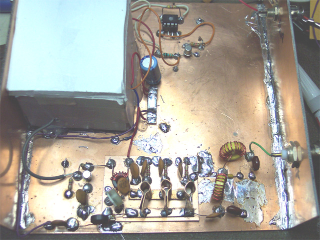
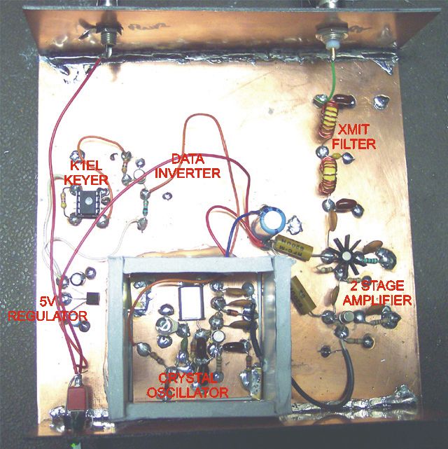
The circuit I used was from Radio Amateur 9H1LO Website along with G6AVK' website. I built it using the "manhattan style" of construction. The Oscillator section is mounted in a Foam box constructed from foam core display board to try to keep the temperature stable and the oscillator from drifting too badly. The keyer chip was supplied from K1EL K-id and works very well. The keying ouput was opposite from what I wanted so a one transistor inverter was added to make the keying "right side up". I am presently using FSKCW keying at a 3 second dot rate. I may be changing this around to improve my DX rate. There is still much to learn about this mode of operation and study. This was a really fun project. Now it will be very interesting to see where the reports come in from of the people who copy my signal. Further information will be posted as the project progresses. |
|
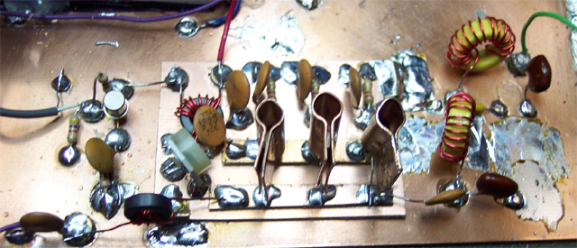 |
First Modification was to replace the
single 2N2222 final amplifier with something that had a little more power. I chose the circuit used by K8IQY as used in his 2N2/40. It uses three 2N2222 transistors in parallel. It fit into my transmitter case with some minor moving of other parts of the circuit. I now put out 900 mW and hopefully, I will be seen in England, Belgium, or Australia. The white Pot on the left corner of the board allows me to adjust the power very smoothly from about 100mW to 900 mW. The homemade copper heatsinks will prevent early death of my transistors but at the present time they seem to be adequate. |