|
Well, I just couldn't stop. I gave up on
model 4 in the middle of development and am now busy building
MODEL 5. It is the brain child of Ross KB1KGA. His website is: This picture has the new single transistor
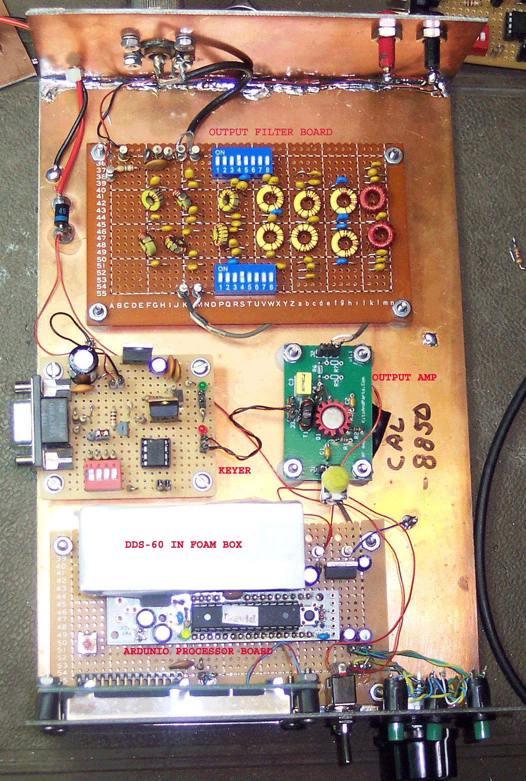
Output Amplifier from Diz's collection of RF Tookit modules: This RF amplifier works very well in continous service giving me about 170mW of power output with 13.8VDC applied. The added heatsink is required for continous service. The PICAXE 08M keyer was built for the
80 second dits testing in October of 2010. |
 |
 |
This is another view showing the front panel
with the readout displaying the frequency. The big knob on the
right is the shaft encoder to change the frequency and the three
green push button switches are the function switches that change
the modes, provide an enter function, and control the frequency
steps for the encoder. The toggle switch is the on/off power switch and the little green LED is the power indicator light. The readout display is also Lit when the unit is on so the little green LED is a bit of overkill. The readout I used was a Lumx Model LCM S01602DSR/B which I got at DigiKey Part# 67-1769ND for $11.38 each. I found no errors on Ross's schematic and I used the 3rd update schematic and software. I built the controller on the holed Hobby Board with the single solder circles around each hole and wired it with some left over wire wrap wire that I soldered to the terminals. I used an RBBB Ardunio Kit board from Modern Device and when I built the kit I made the pins point down. Then inserted them into SIP sockets and put them into the hobby board and soldered them. I used right angle pins on the LCD Readout and did the same thing. The DDS-60 which is also available as a kit from the American QRP Club was mounted the same way. Then I turned the board over and did the wiring. On one end I also made SIP plugs for the encoder and function push buttons. It came out as a nice, neat, and functional module. |
|
The Filter board was built on the same type
of Hobby board and the dip switches on either side select the
different filters. I will try to supply a diagram of this in the near future. It also has a 50 ohm dummy load and a power monitor probe built in so it is easy to adjust the power output. A filter for 80/40/30/20/17/15/10&12 Meters are installed on the board. They were designed using SVC Filter Designer 2.11 from Tonne Software and was a bonus on the CDRom that came with my 2010 ARRL Handbook. The software worked very smoothly and every filter tested out to the same curves that I had printed out when I was using the software. I used some Monolithic Capacitors from JAMECO Electronics. (Only place I could find them in the values I needed) |
 |
 |
I have already modified this unit by
changing the transmitter board to a single transistor RF amplifier
Kit sold by : http://www.kitsandparts.com/rfamp1.1.php It is a one transistor wide band amplifier to which I added a heat sink to the transistor. I also use a pot to control the drive power to the little amplifier. I can get about 170mW at 13.8VDC which is more than enough to work the world on this mode. Not bad for $8 plus postage. It seems to handle continous key down service very well. I have not had one failure of this amplifier since I put it into service over 6 months ago. |