K5AM
k5am home
FT-1000D Subreceiver BPF antenna
modification
1. Problem. The main receiver
may receive signals from
either the main antenna jack, or the RX ANT jack. A switch
can be used to make this choice. Also, the subreceiver may
receive signals from either the main receiver front-end (and
whichever signal source the main receiver has chosen) or
from the SUB RX ANT jack at the back of the BPF unit. A
switch can be used to make this choice.
The problem is that there is only one switch on the
front
panel for these two independent choices. A little switch,
S1001, on the RF board selects which function the front
panel switch will control. The function for the other antenna
choice is then completely lost.
Most operators choose the setting which allows the
front
panel switch to control the main receiver antenna. Then the
subreceiver is permanently connected to the main receiver
front-end; this leaves the BPF out of the circuit, and limits
the frequency range of the subreceiver, as in the MP. In the
words of one ham (sorry, I forget who it was, but will update
this note if you remind me) in a recent Yaesu e-mail list
posting, "The BPF is totally worthless."
[Added note. After
I wrote this up, I found a copy of
an old list posting which solves the problem in a
similar manner. There have probably been several such
notes posted. Anyway, the method described here may be
slightly different, and possibly useful.]
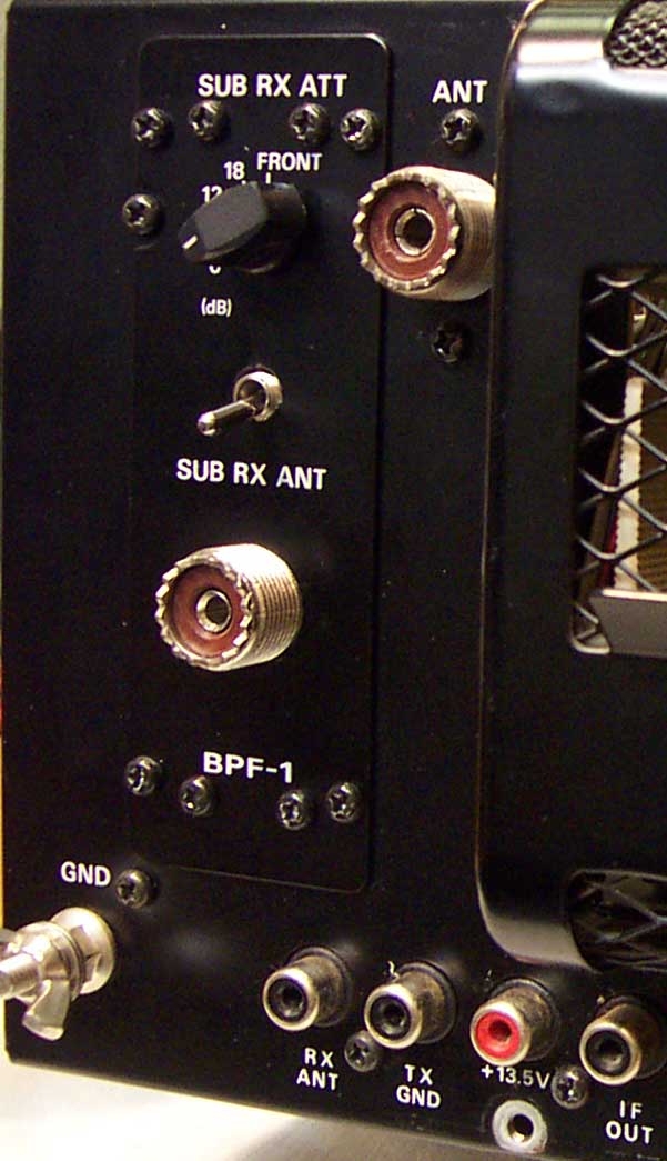
2. Solution. Add another
switch. This switch will work exactly
as if it were the front panel RX ANT switch, and as if S1001
were set for the subreceiver.
The modification is electrically extremely simple and
quite obvious; the only effort is in mounting the switch and
connecting the wires. The new switch is added on the back of
the BPF unit, between the attenuator switch and the
subreceiver antenna jack. The modification requires no
circuit board mods, no surface-mount work, and only a few
parts.
Drill holes in the radio? Horrors! Well, I never
worry
about resale value. Why would I ever sell such a great radio?
Anyway, a knowledgeable buyer would appreciate the
modification. The switch is quite inconspicuous. In any event,
the holes are not in the radio proper, only in the hidden BPF
chassis, and in the little black replaceable cover.
3. Operation.
a. The front panel switch controls only the main receiver.
b. The rear switch controls the subreceiver. No labels are
needed on the switch. DOWN towards the antenna jack
selects that jack, and what is usually the lower antenna, such
as a Beverage. UP selects the main receiver antenna source,
and what is usually the upper antenna, up on a tower.
c. In most cases, the RX ANT and SUB RX ANT jacks can be
tied together with adapters and a short jumper and
connected to one auxiliary antenna. This will allow the
auxiliary antenna to be used with either receiver, or both at
once.
4. Materials.
a. One miniature switch, SPST, 1/4 inch bushing. Single pole;
double pole would be too wide. A sub-miniature switch, 3/16
inch bushing, might be even better.
b. Two pieces hook-up wire; 24 inches and 2 inches. Not too
heavy or thick. #24 stranded, 0.010 inch insulation. Alpha
#1854 is okay. Best is Alpha #7054, irradiated, soldering-
iron resistant, Mouser #602-7054-100-01,
www.mouser.com.
c. Two small cable ties.
d. Five baby food jars to hold different types of screws.
5. Installation. This
procedure is not specified in great detail
here, but hams with experience working on the FT-1000D
(this does not include me) will find the modification very
easy. Radios from different production runs may have
differences in layout; they might not correspond to the steps
below, and require slight changes in the procedure.
5A. RF board.
Remove covers from radio.
RF board is to be lifted sideways.
Remove three coax cables near outer rear corner; sketch
positions, cut off cable tie.
Cut off cable tie from large wire bundle at outer front.
Remove cardboard shield.
Switch S1001 to R ANT.
Remove three screws from rear, which hold connectors. Note
that one is machine, two are taping.
Remove board screws and lift board sideways.
Strip and tin one end of long wire only 1 mm; tack onto outer
terminal of S1001; this is the E BPF terminal.
Run wire up to board top through the unused corner hole.
Replace board; shield, 6 board screws, 3 rear screws.
Replace cables.
Replace two cable ties.
Feed wire up along corner, and over above BPF.
5B. BPF.
Remove BPF unit.
Remove black mounting plate.
Remove shield.
Remove BPF board from BPF chassis. Lead unsolders from
coax connector, which stays on chassis.
Drill hole for switch in BPF chassis lip between attenuator
switch and coax connector. Removing the BPF circuit board
ensures that all drilling fragments can be removed from the
chassis - one fragment can kill a radio.
Drill matching hole in black cover plate.
Attach switch to chassis; body close to lip, no spacer nut
inside chassis. Orient switch according to convention noted
above.
Install BPF board. Attach black plate.
Connect one side of the switch to +13. There is a convenient
fairly large +13 pad on the relay sub-board; it is easy to
locate because there are only four leads to the sub-board:
two antenna leads, a ground lead, and the +13 lead. Early
versions of the BPF might not have a subboard.
5C. Final installation.
The wire is fairly long for two reasons. One is installation
convenience. The other is to allow slack in case the RF board
is to be lifted in the same manner at a later date.
Position the BPF unit on the workbench behind the BPF
opening.
Run wire up in corner, over and above BPF area, out through
opening, and into the BPF chassis through the cutout for the
two connectors.
Attach wire to switch. ON should be with the switch toggle
towards the coax connector.
Attach BPF shield.
Install BPF unit.
Look for left-over hardware and things that I forgot to
mention.
6. Note. The setting of switch
S1001 on the RF board should
not be changed to E BPF after this modification is installed.
There is no reason to do so. However, if
the switch is set to
E BPF, and the new
subreceiver antenna switch is set for the
subreceiver antenna jack, and the
front panel RX ANT button
is pressed, then Q1026 will receive 13 volts from two
different sources, connecting these sources together. These
are probably ultimately the same source (I didn't bother to
check), so it would be okay, but it's not a good idea. (The
schematic on page 29 of the operating manual is only a
simplified version, and is totally misleading.) Removing
S1001 would eliminate any hazard (and eliminate the most
unfortunate component in the radio). A drop of epoxy
cement, or red nail polish, on the switch to freeze it would
be the easiest solution.
2003 October 17
 k5am home