| The Model 2 MEPT was a continuation of the Model 1's design except it was made in modular fashion. I broke the schematic down into functional modules and built them one at a time and then put the modules together in building block fashion on a larger plate of PC board. This proved to be very useful and provide some ease of construction. Some of the sections could be completed and tested for operation before being mounted in their position on the plate. The Model 2 also had a temperature compensated Crystal Oscillator that was built from a schematic by M0AYF. This made the MEPT very stable in frequency. For the newcomers, Most QRSS's MEPT transmitters never run over 1 watt of power and since our frequency band is only 100Hz, drift very little. Most strive to keep the drift to less that 10 Hz. It keeps you from covering up your neighbors. Another reason for building modules is that when you wanted to change your MEPT, you could do so by building a new module and substitute it for the old one. |
|
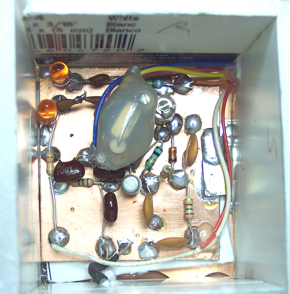
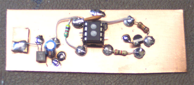
Oscillator Section The Oscillator section was built on a small piece of PC board measuring about 2 and 1/4 inches square. The layout is a little cramped but can be done easily using "manhattan style" construction with almost any reasonablly sized parts. I usually start in the middle with the transistor and then work out from there. The two LED's are used as Varractor diodes and work very well in this application. The Crystal has already been sealed up in Hot Melt Glue with it's 100 ohm Heater resistors on the sides of the crystal and it's 2N2222 transistor sensor which was superglued to it's side to make construction easier. Then the oscillator board is mounted on the base plate board which is 6 and 1/4 inches square with a 2 and 2/8 inch front panel soldered to the base. I put a piece of foam board underneath the oscillator and then grounded it to the base with brass shim stock strips. then build the foam board sides and top to insulate the whole oscillator section from any changes in temperature. |
 |
|
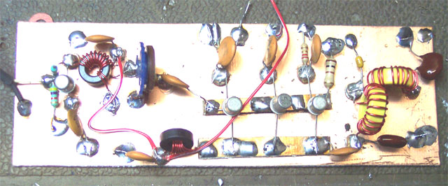
Buffer/
PA Section
|
 |
|
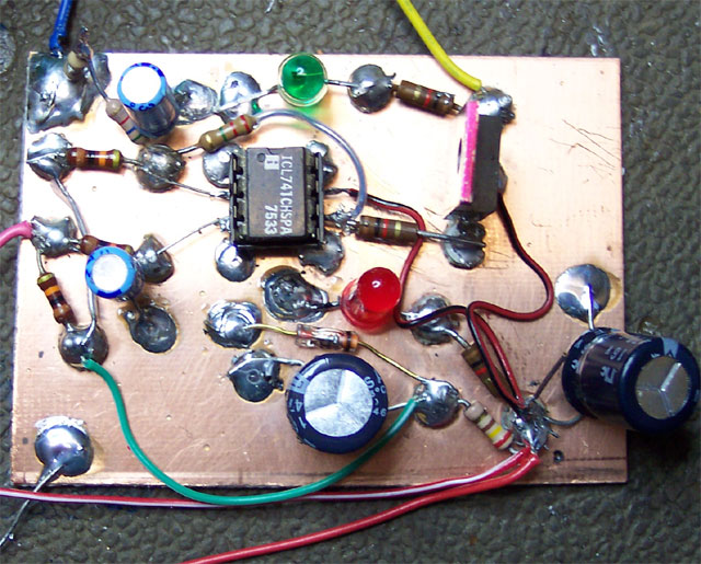
Crystal Heater Section The Crystal Heater controller section is built on a 2 and 3/4 by 1 and 7/8 inch piece of PC board. I laid this one out about the same as I did the Oscillator section. I positioned the 741 OpAmp in about the center and built the rest of the circuit around it. I did think about putting the two indicator LED's on the front panel and may move them later but for now with the open base, I can peek in and see that they are lit. I did use a socket for the 741 OpAmp. This could be compressed more but I had the room so this is how it turned out. I used the Model 2 Crystal Heater from M0AYF. The crystal heater schematic came from HERE |
 |
|
Keyer and Power conditioning
circuit I have modified this keyer module using a PICAXE 08M processor and added some features for controlling the transmitter Push to talk. That makes many different types of QRSS modulation possible. Programs are available for the new keyer/power conditioning module for FSKCW and Very Slow CW keying on the order of 80 second dits and 240 second dahs for extremely low power operations. The new Keyer Schematic is found in the schematic package available below. I am slowly developing programs for the keyer as I need them and they are available for the asking. If you develope a keyer program for this keyer that you would care to share, I would be glad to archieve it and make it available with my programs.
|
  |
| The schematics are found HERE in .PDF format so that they will be easy to print out. I found that the ExpressPCB Schematic drawing program (a free download) makes an excellent tool to draw schematics for projects like this, So, They are now redrawn in that format, copied and then put in .PDF format so they can be viewed on almost any Personal Computer. |
BACK PANEL 2 and 3/8 by 6 and 1/4 inches with BNC RF connector and a Phono plug for power installed. 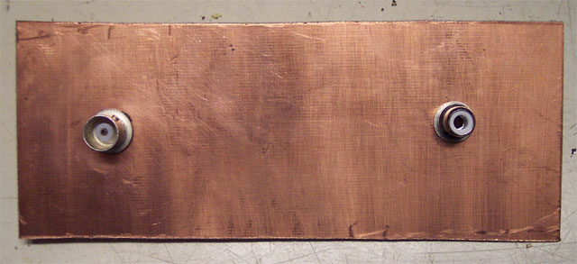 |
|
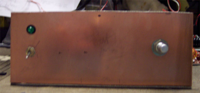
Front Panel Size 2 and 3/8 by 6 and 1/4 inches with the power LED and switch on left side and pot for fine frequency control on the right. This board along with the back panel is just soldered along the bottom to the base plate PC board. Then the Oscillator is installed. Then the back panel and then the rest of the modules are put on the base plate as they are completed. I use strips of brass shim stock to provide a good low inductance connection to the base plate by attaching the modules in at least two places to the base PC board. If you need to make a change later on, Just remove the module and make your changes and then put it back. Makes it real easy for projects like this one. |
 |
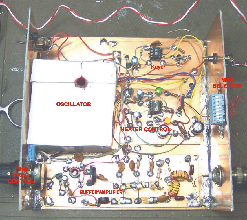 |
Here is the finished MEPT transmitter. It really is easier to complete in modules as you can work on one module at a time to make construction easier. When all of the modules are completed then you can combine them to make a completed unit. It seems to break up the construction into managable steps and also allows you to check out each module as you complete it. It starts with doing the Oscillator first, then the Heater Control unit, then the buffer/amplifer, and last the keyer and power wiring. |
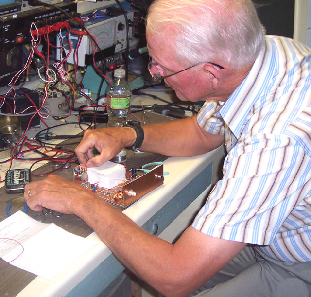
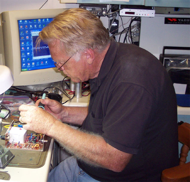 Here is the constructor of the first Model 2 MEPT transmitter. This is my buddy Perry KC7VHS. You will see his call around the world from his home brewed MEPT transmitter. He is operating it on a Butternut HF-6V with twenty 22 foot radials mounted in his back yard . I think he really enjoyed building it and did a really good job. The module pictures are from his transmitter. This was his first BIG building project and is proof that if you take your time, You to can build a nice stable MEPT transmitter in about a week's time. |
|