TEN TEC 555 SCOUT
TEN TEC 556 ARGO
MODIFICATION NOTES
The NA5N
The NA5N modified Scout (optimized for CW and QRP/QRO)
CW AUDIO FILTER & ZERO-BEAT MODIFICATION
Discussion. I've built and added CW active audio filters to almost every QRP kit or homebew rig I've built, including my Ten
Tec 540 Triton IV years ago. A properly built active audio filter with low ESR capacitors can make a profound difference to CW reception. It
is basically an audio bandpass filter that forms a narrow pass band centered on the 700Hz CW offset (or as desired). An "active
filter" uses op amps to provide the gain and feedback for establishing the center frequency, Q and bandwidth. The narrow bandwidth
enhances the desired CW tone, attenuates or rejects nearby audio frequencies (nearby stations) and reduces the band noise
to improve the signal-to-noise ratio.
I have long contemplated adding an active CW audio filter to the Scout. There's not much
spare room in the Scout, as you know, but I wanted the filter to be internal, not in an external box. Becoming somewhat
tone deaf in my old age, I also wanted to add a 700Hz tone decoder as a zero-beat detector. It was quite a project, but the addition
greatly improves the Scout performance on CW.
MODIFICATION BUILD STEPS
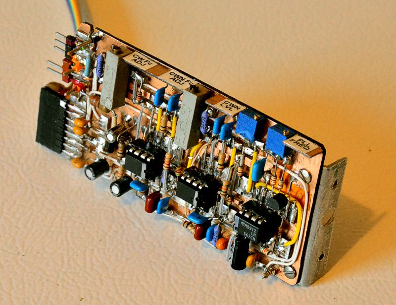
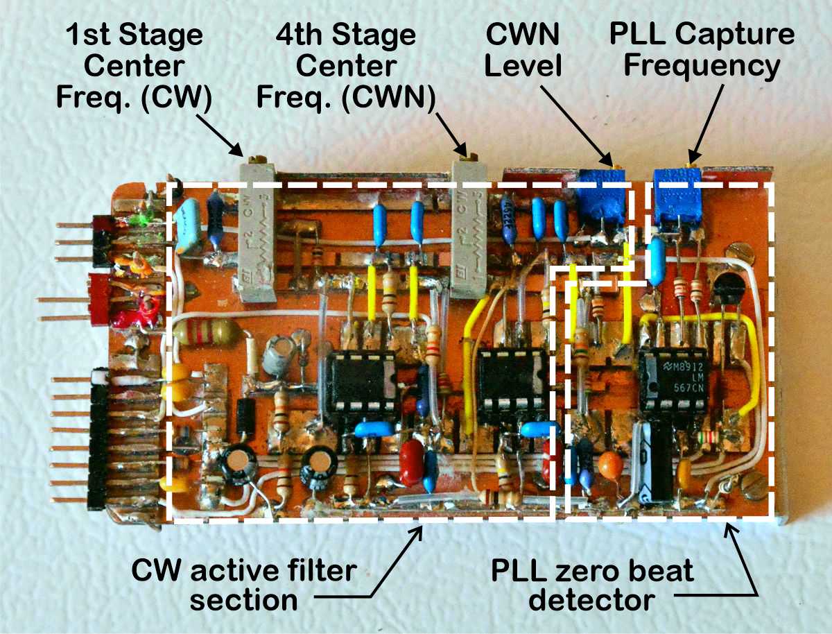
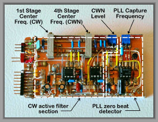
Built the CW active filter and zero-beat detector on a 2x4 inch copper clad substrate. It was built "Manhattan style" by using super glue
to affix small pieces and strips of copper clad for component mounting and the electrical connections. I used NE5532 op amps, an
LM567 PLL (phase locked loop) tone decoder for the zero-beat detector, and IDC ribbon cable and connectors for the interface wiring.
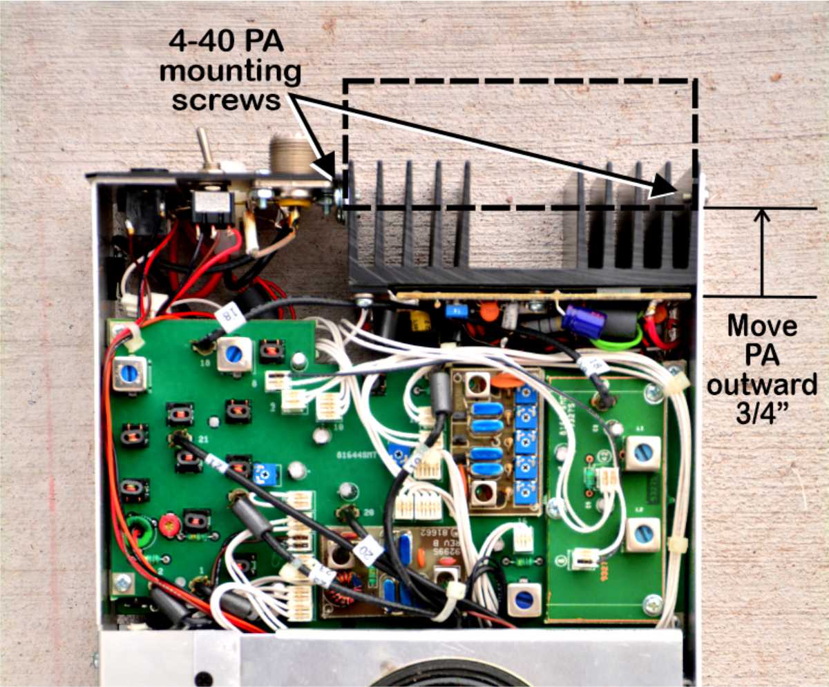
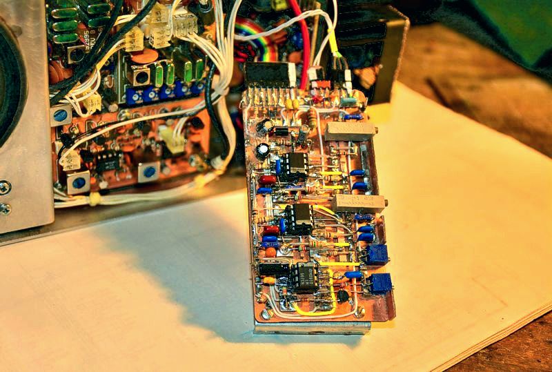
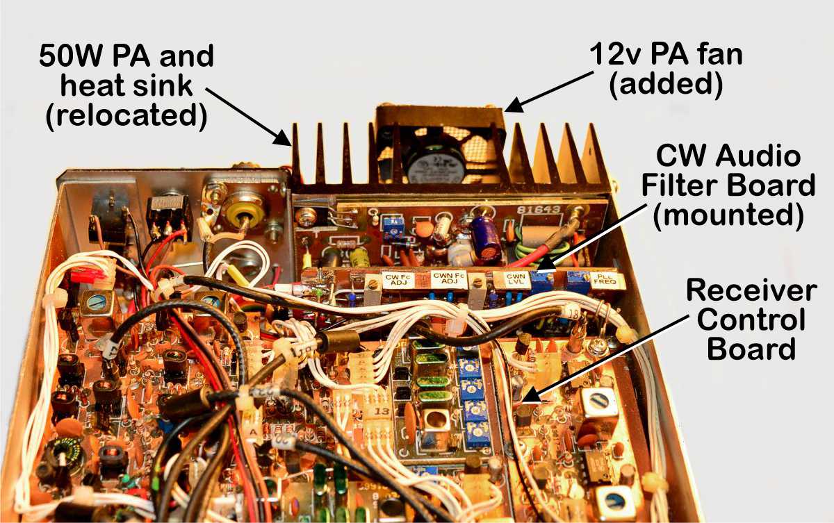
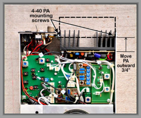
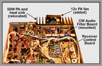
I decided the only place to mount the filter PCB was to mount it vertically between the 50W PA assembly and the rear edges of the Receiver
Control and LLD boards. To accomplish this, I had to move the PA assembly and heat sink outward about 3/4 an inch by drilling and
tapping new 4-40 holes in the heat sink to re-mount to the Scout rear panel pieces. Photo shows surface mount version; I modified
my thru-hole version.
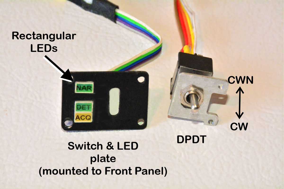
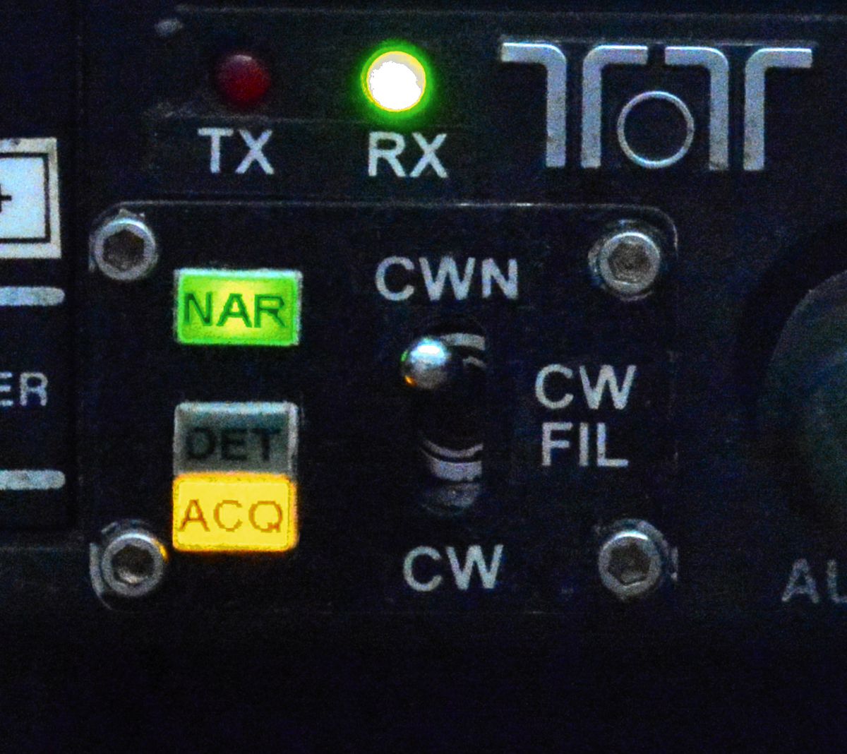
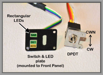
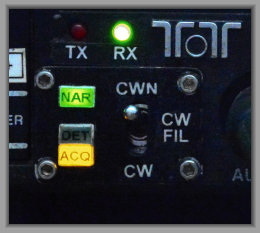
To operate the CW filter, I needed a DPDT toggle switch to select CW (500 Hz) or CWN (NARrow 170Hz) and the indicator
LEDs
on the front panel. I removed the MIC connector and enlarged the hole with a Dremel tool for the small switch plate and
DPDT switch. The slot for the switch was to match the other Scout toggle switches.The MIC and SSB stuff was redundant as this has
always been a CW only Scout.
Step 1
Step 2
Step 3
Step 4
Step 5
Step 6
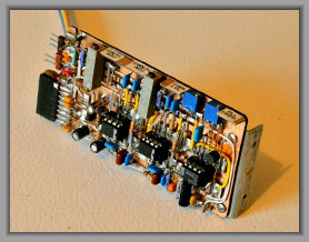
Completed CW Filter assembly. The 2x4 in. copper clad circuit board is mounted to a piece of aluminum about the same size with a mounting
bracket bend. The mounting holes are tapped 4-40; matching 4-40 thru holes drilled on Scout right side chassis for mounting.
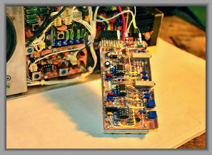
The CW Filter assembly with connectors installed and ready to mount in the Scout. Wiring to the front panel switch
and LEDS, and audio wiring to the IF/Audio board completed. The CW filter was checked out on the test bench with an audio oscillator
prior to installation.
Installation complete. The CW Filter assembly mounted in the Scout between the Receiver Control Board and relocated 50W PA. It
is held in place with 4-40 binder heads to the right hand chassis. A tight fit, but it worked!
Filter and PLL adjustments on
top edge for easy access without removal.
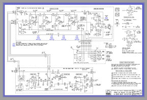
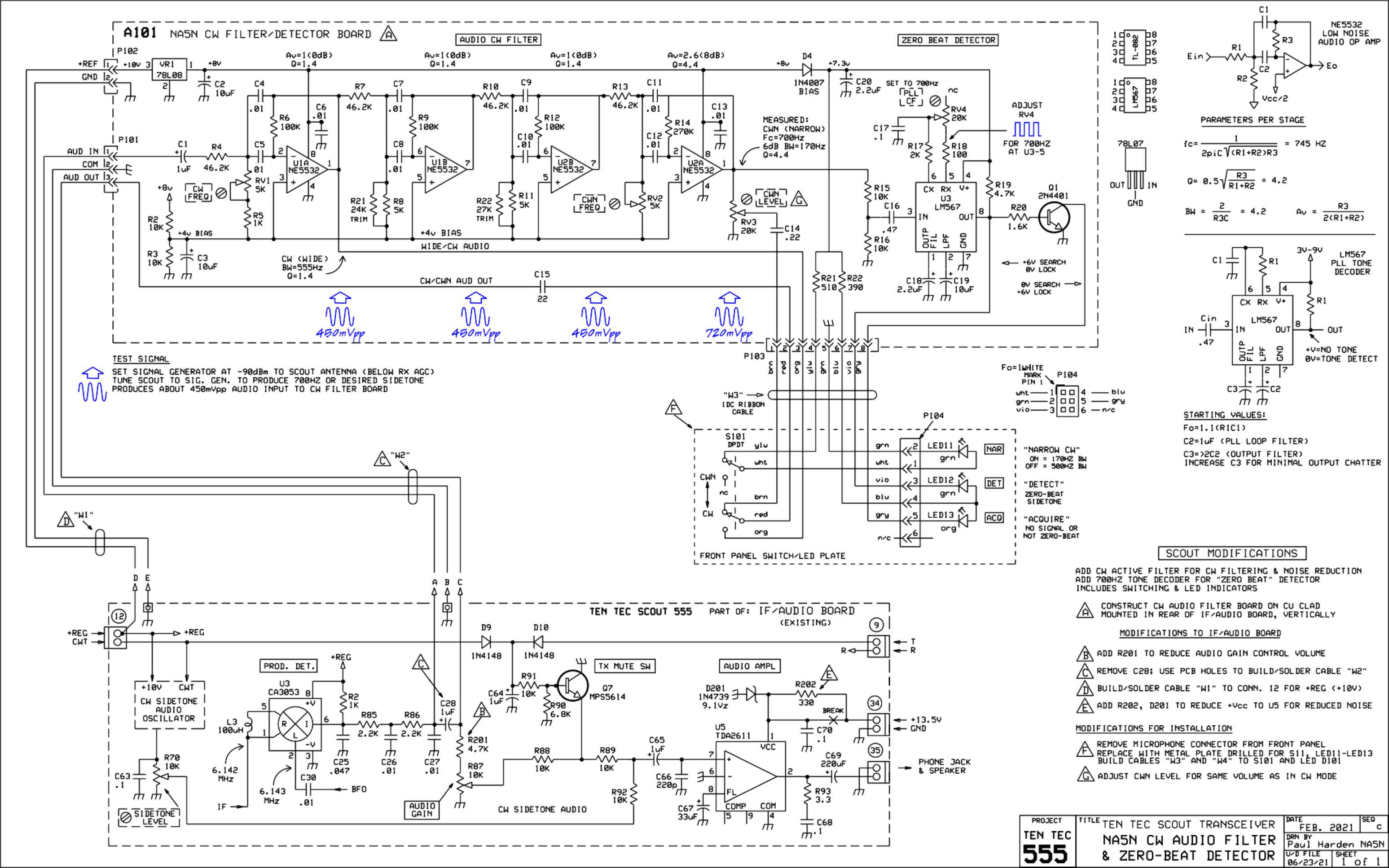
SCHEMATIC diagram of the CW Filter and Zero-Beat Detector board, and
modifications to the IF/Audio Board.
Step 7
Click photos to enlarge
Switch/LED plate mounted where the MIC connector once was. Plate is .75"H x 1.125"W and mounted to Scout front panel with 2-56
socket head screws, 2-56 holes tapped into front panel plastic for easy removal. Painted flat black. Labels made with a graphic
program, printed on matte paper and glued in place. Blended in well.
OTHER MODS
PA Power Control, reduced audio, etc.
to be documented shortly.